-
Final Drive Rebuilt for CJ750 / M72 - Assemble The Ring Gear
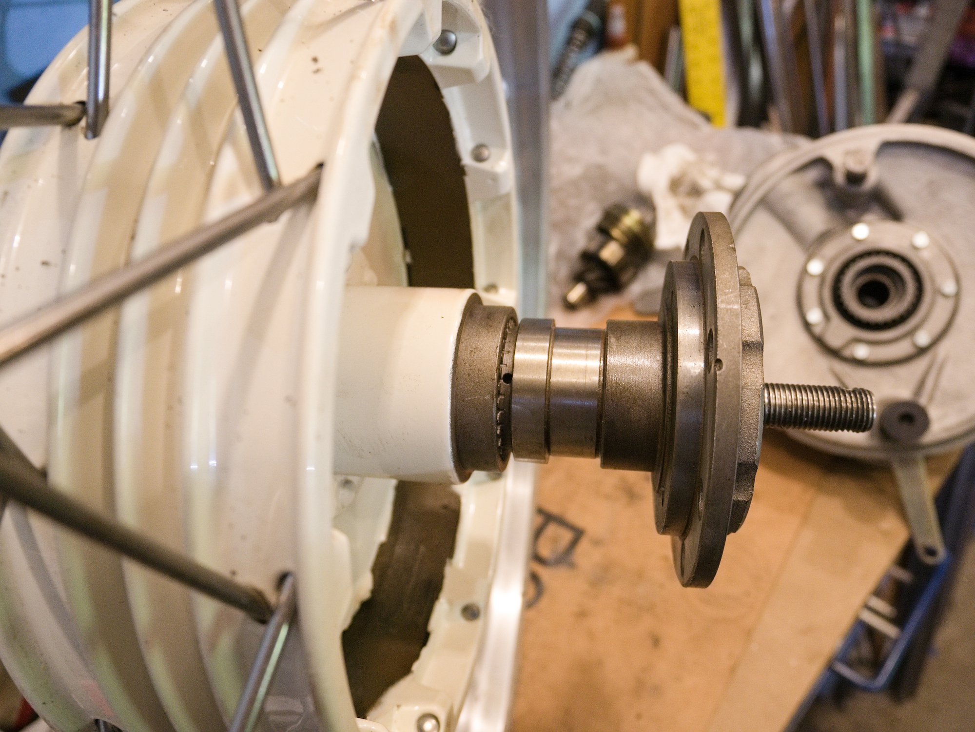
The distance bushing is made out of 1"x0.12"x0.76" DOM Mild Steel Tube A513 and drilled to an internal diameter of 20mm on the lathe. The old one was rather sloppy and was not perfectly even.

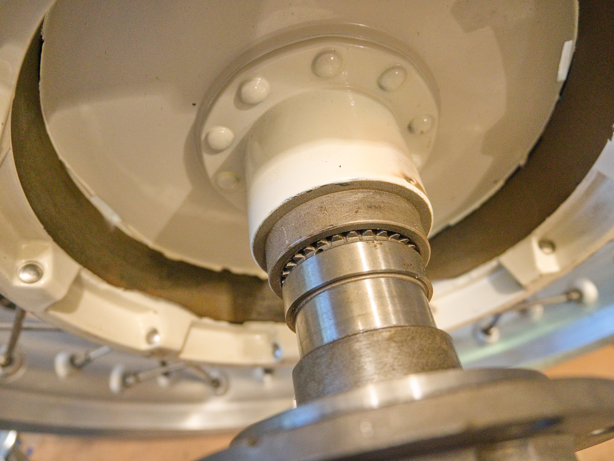
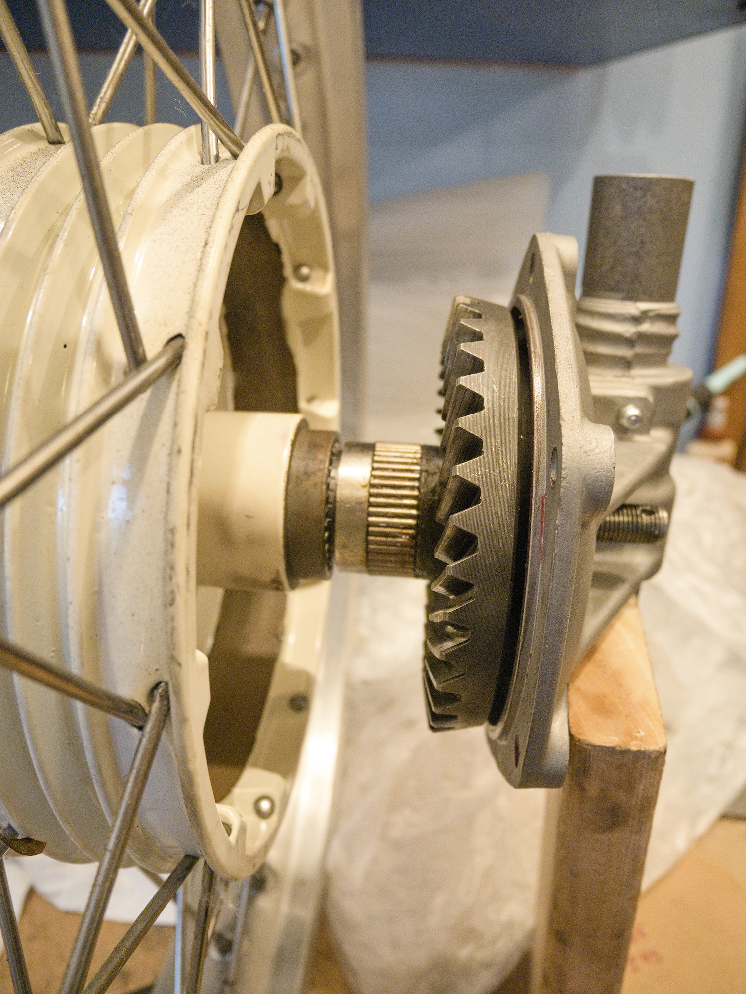
Check the distance and the seating of the driving gear. I have put a large o-ring inside the wheel hub to push the hub towards the cover. This ensures the ring gear always seats against the cover and maintains proper distance of the gears.
The CJ750 FD does not use the bronze slitted washer to keep a minimal distance between the ring and pinion gear, and with the o-ring on the wheel side, the ring gear never slides towards the pinion.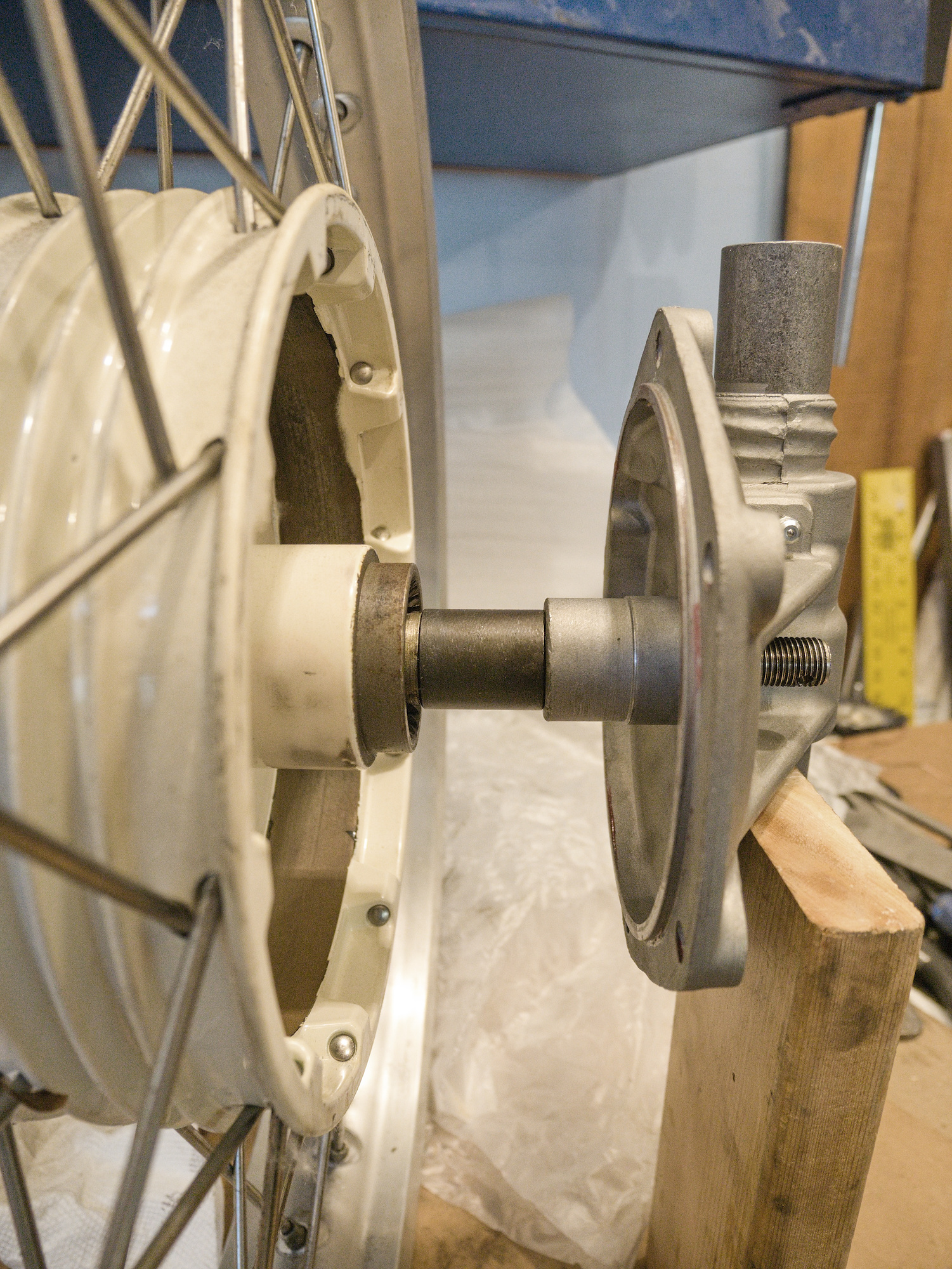
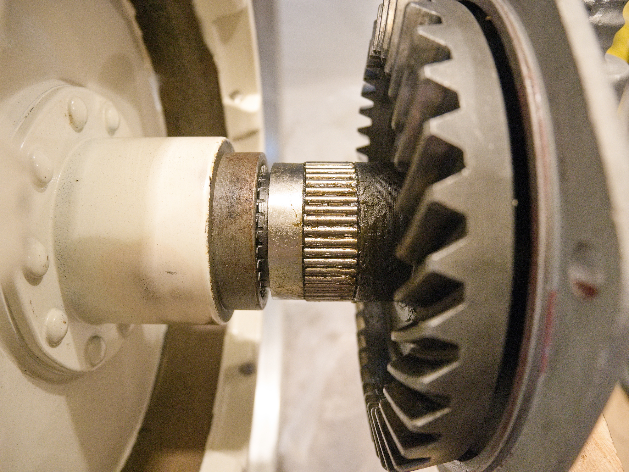
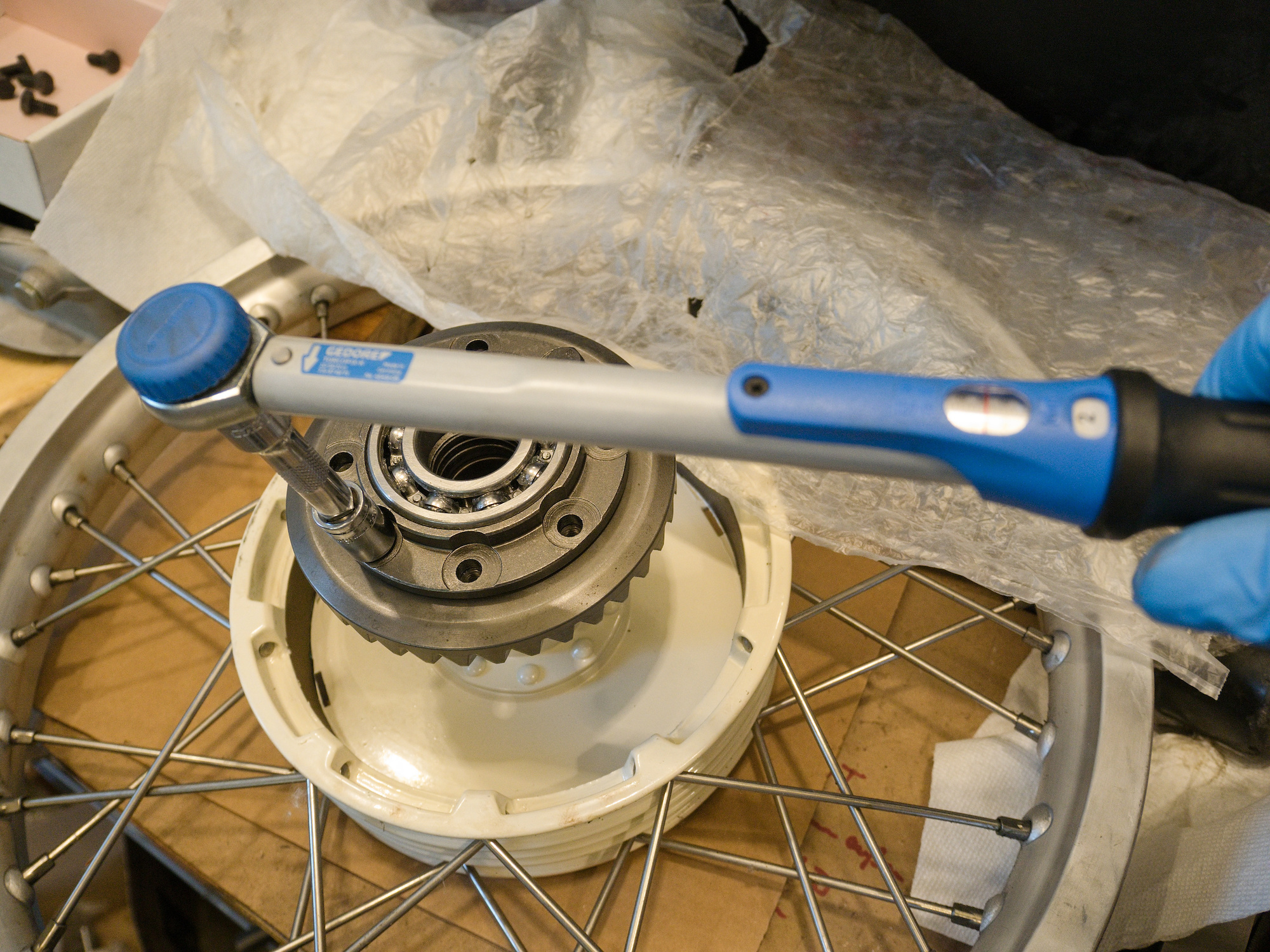
The M8x14 1.25 bolts, class 10.9, to connect the hub with the ring gear are secured with red loctite 272.
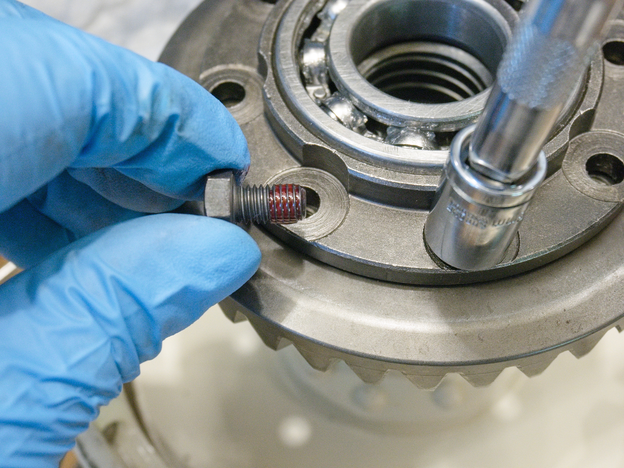
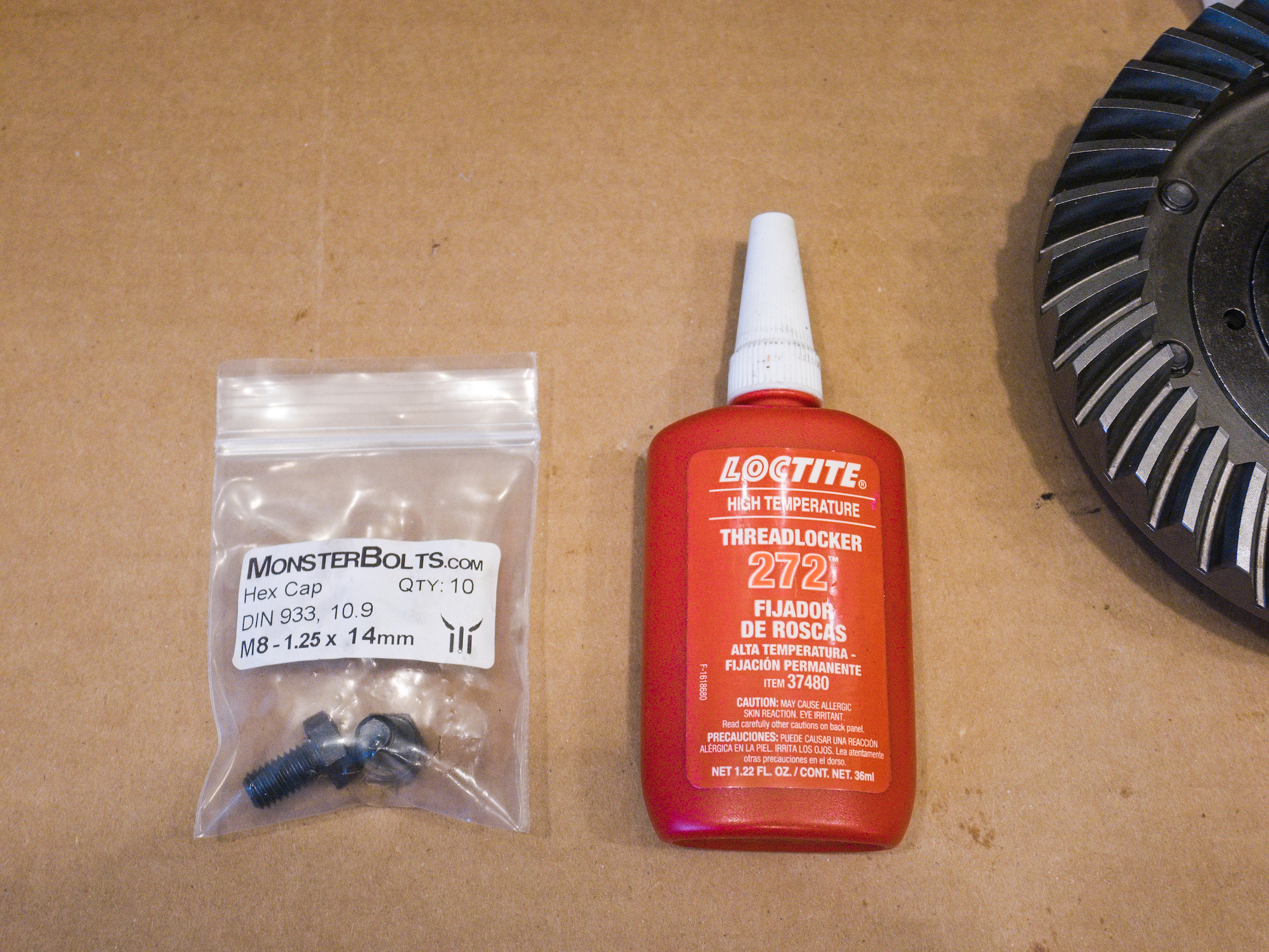
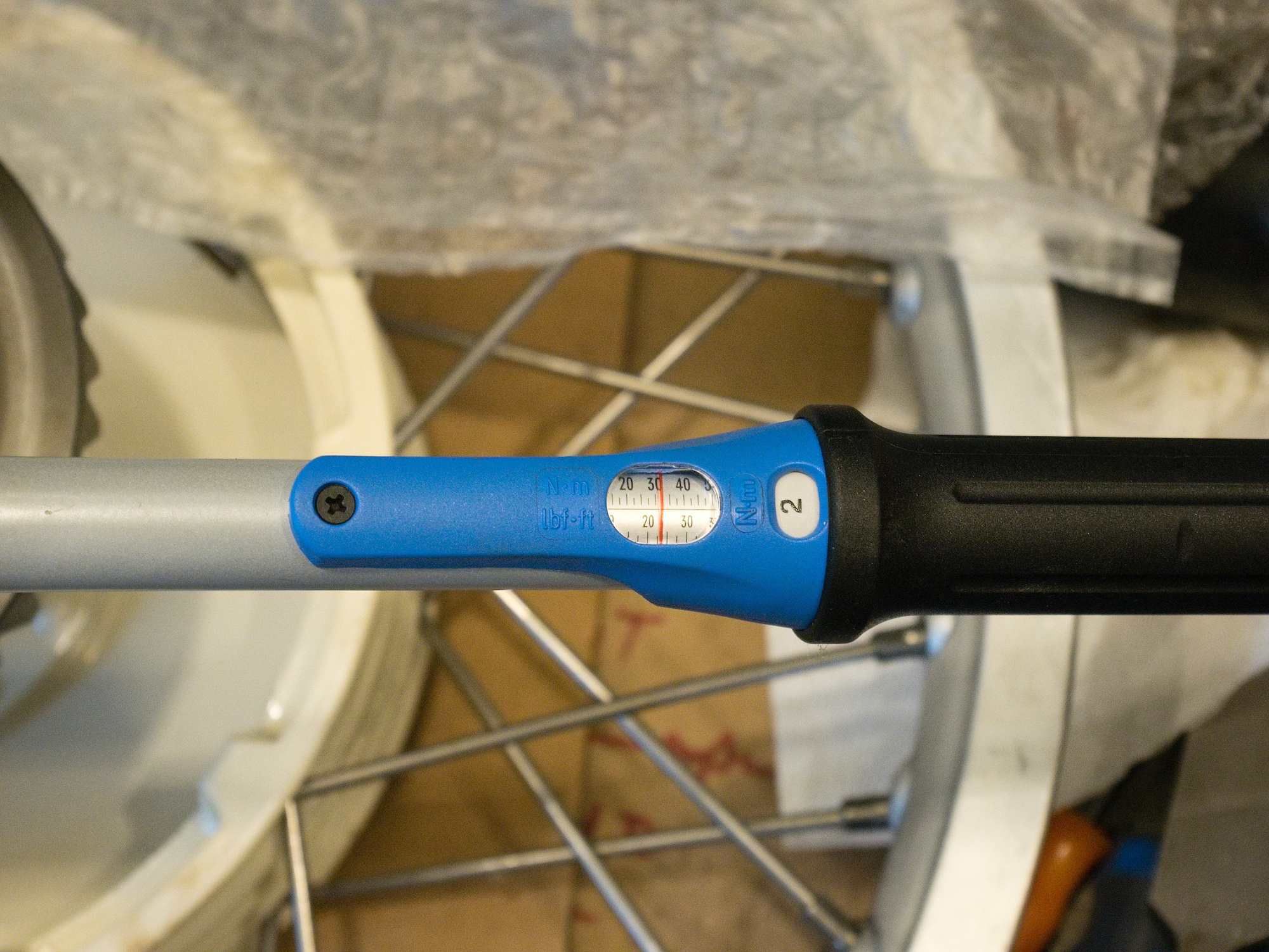
The bolts are torqued to 32Nm.
Clean the casing and cover surfaces and place the seal. Check the orientation as there is only one valid hole pattern. I used the one with EU quality from ural-zentrale.
-
Final Drive Rebuilt for CJ750 / M72 - The Spring
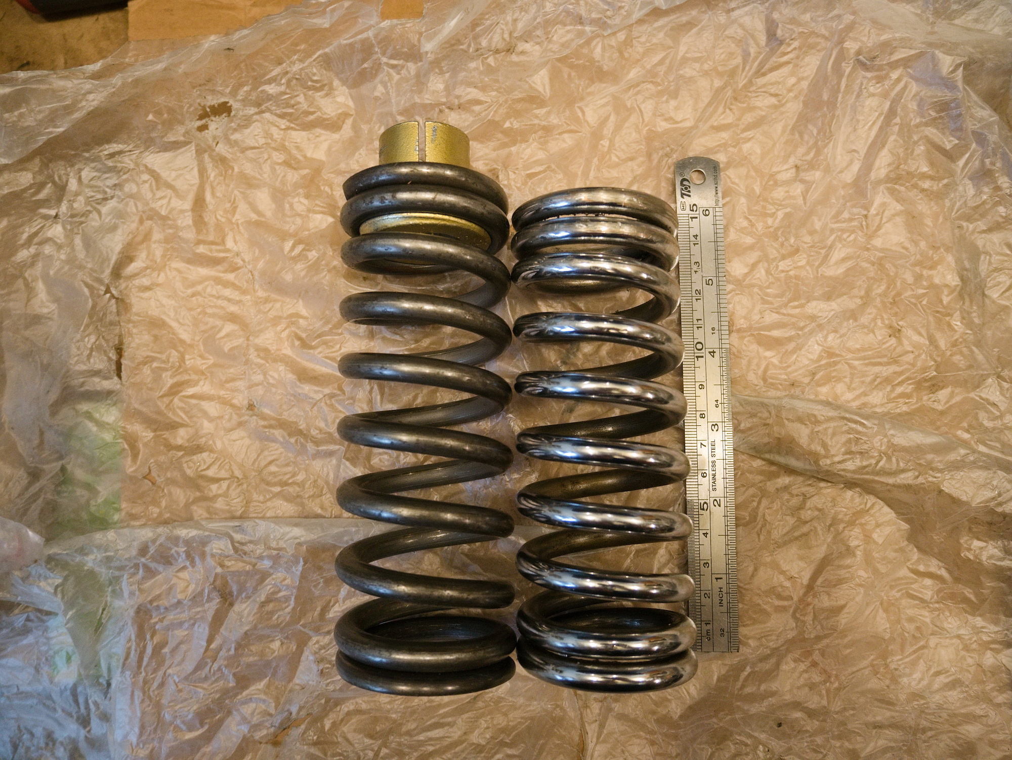
The suspension spring on the old final drive (FD) needs to be removed as it is reused for the new FD. It turned out that the measurement of the new suspension spring is different from the old one. It is only a small amount, but left and right suspension side need to match.
Level 1 of spring removal
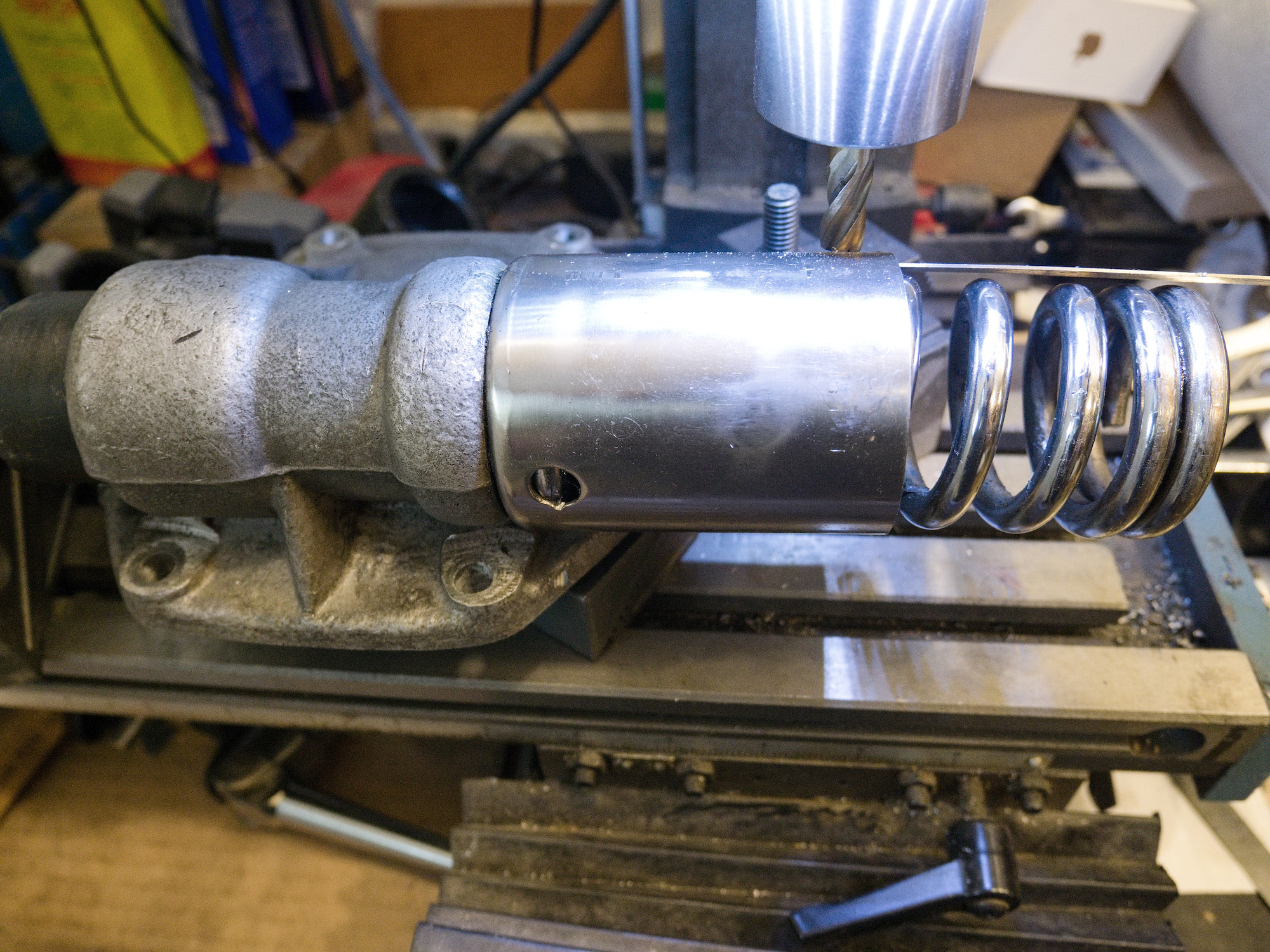
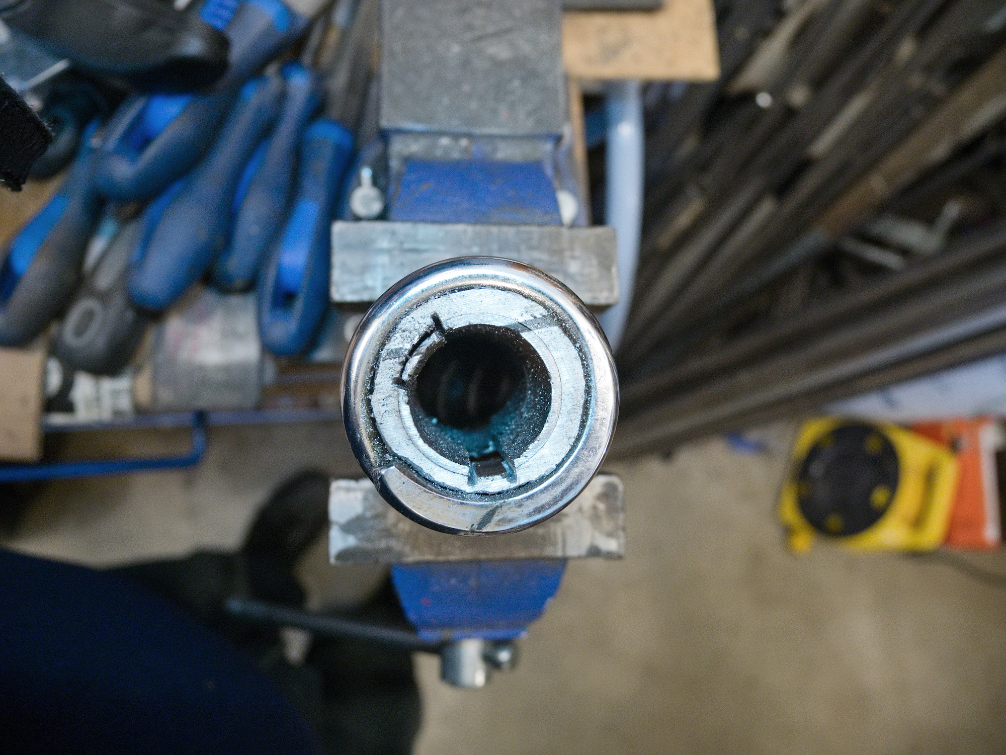
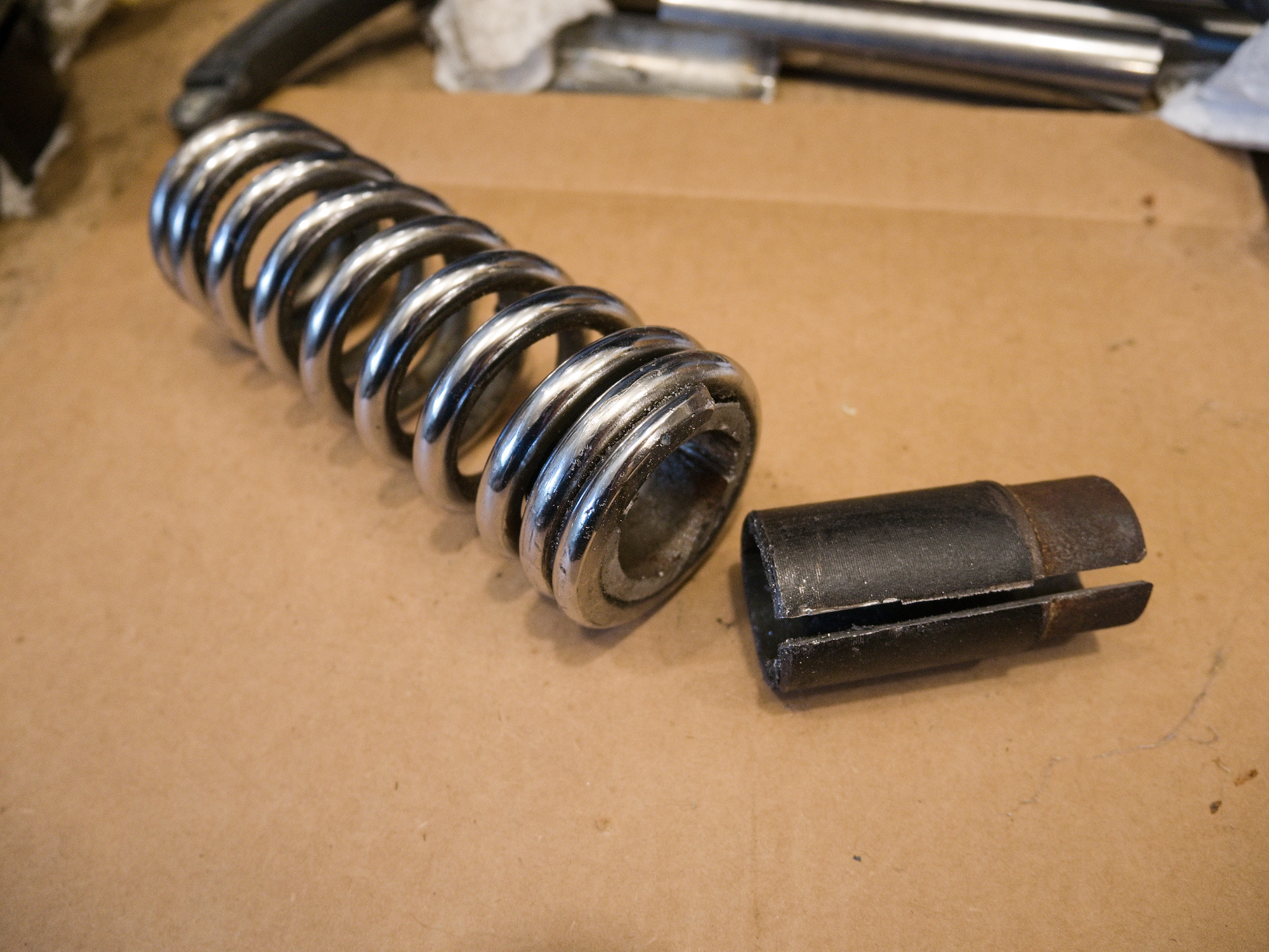
The cap of the spring has a small hole to access the end of the spring and can be tapped out with a punch through the small hole. Simply twisting the spring will not work as the spring tightens when turned. Tapping will move the spring the opposite direction to unscrew from the holder.
Not the case here.Level 2 of spring removal
Small access hole in the cap is not in the correct position and cap needs to be turned to access the end of the spring.
Not the case here.Level 3 of spring removal
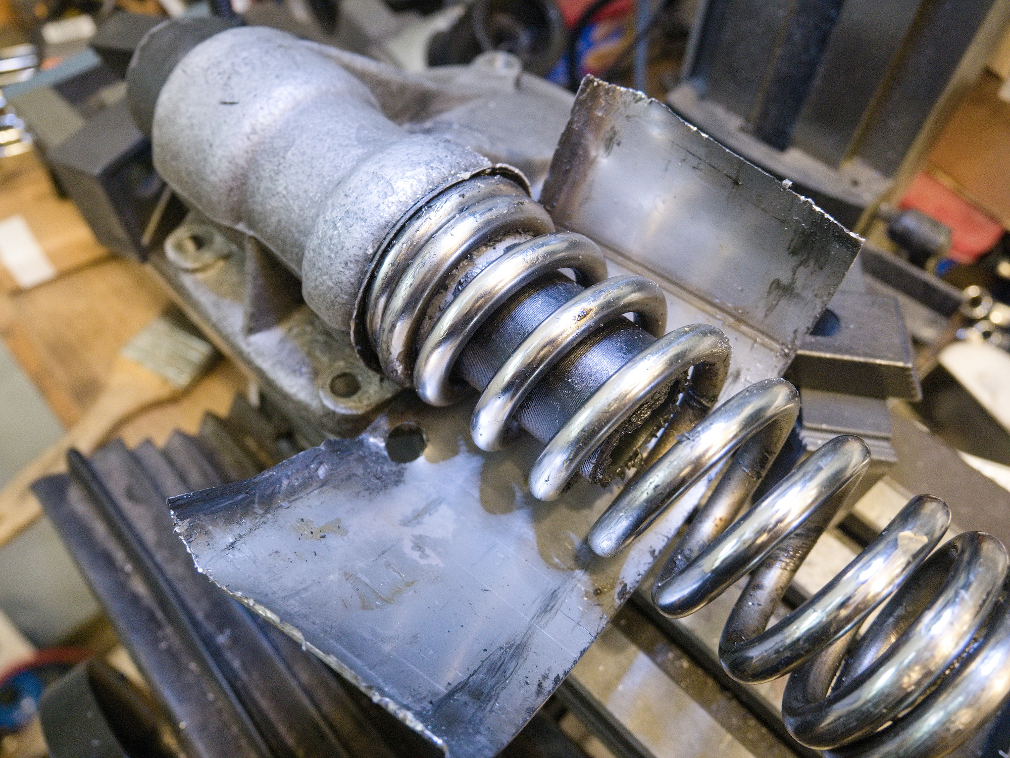
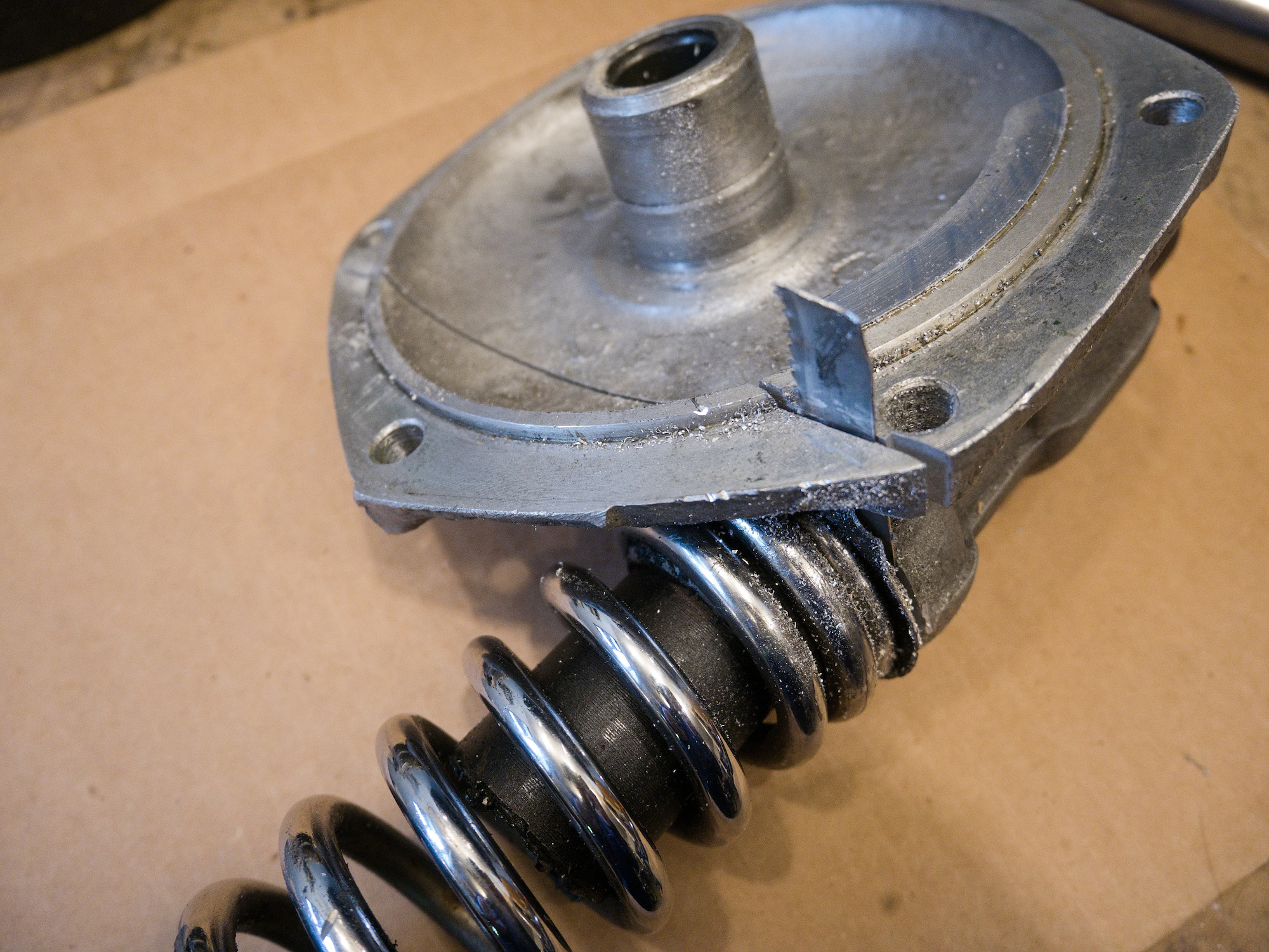
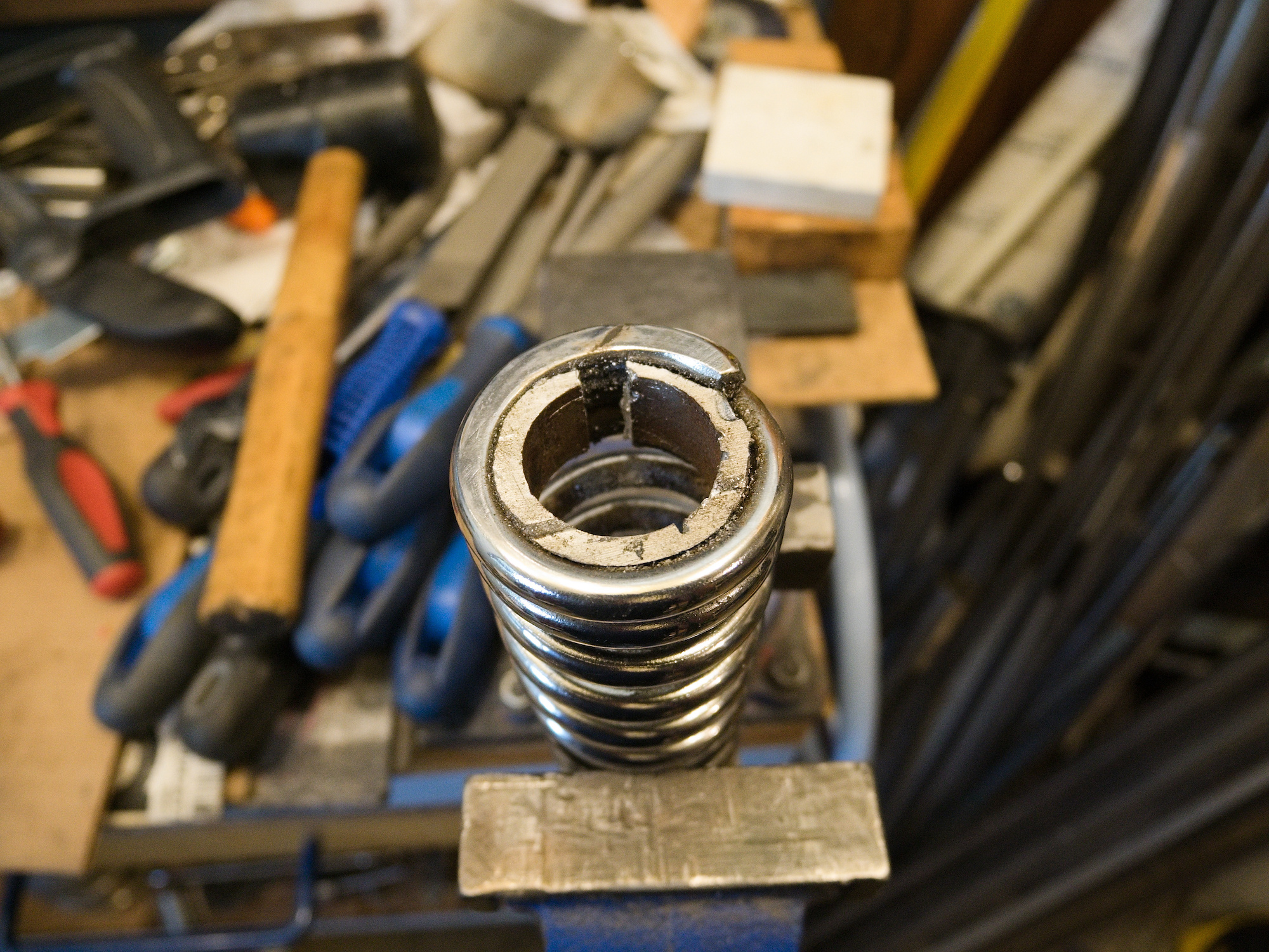
Everything is stuck. The cap will not turn, and the end of the spring is in a position that is not accessible to tap out.
This is the case here.
The surgery starts with the removal of the cap. The endmill is positioned to not cut all the way through the metal to not damage the spring.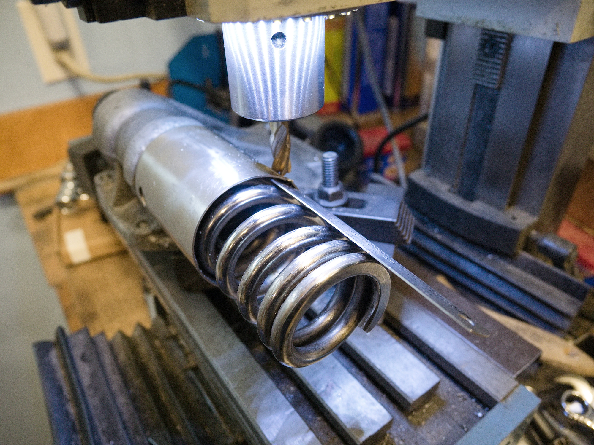
Carefully bending back and forth.
To try to turn the spring, a spanner is modified to hook into the end of the spring.
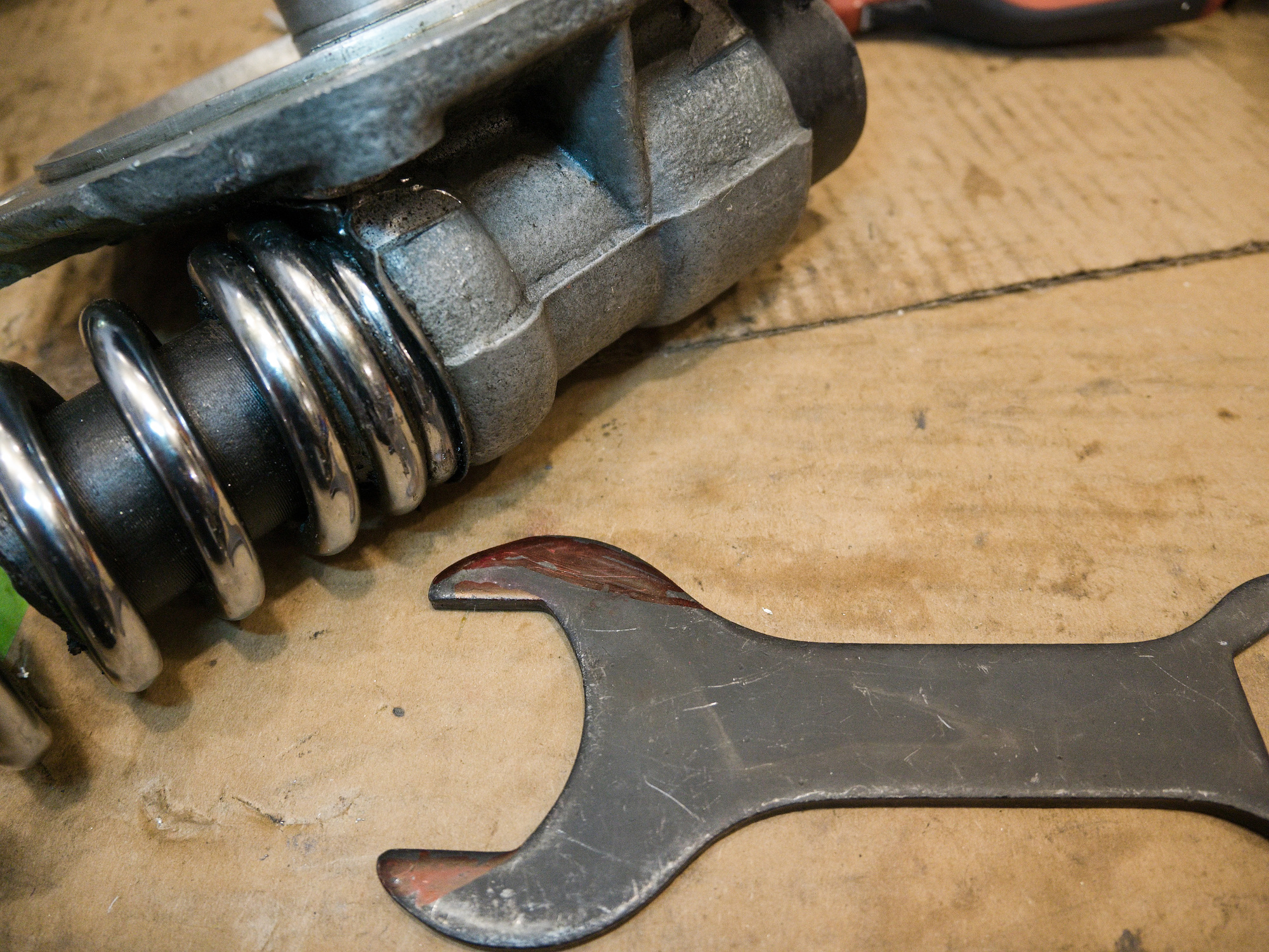
The position of the end of the spring is tight. The spanner need to be rather thin on the end to reach the spring position. Usually it does not take too much force to get the spring started, but unfortunately the spring is too tight and the spanner fails and the end of the modified spanner breaks.
Upgrade to level 4 of spring removal.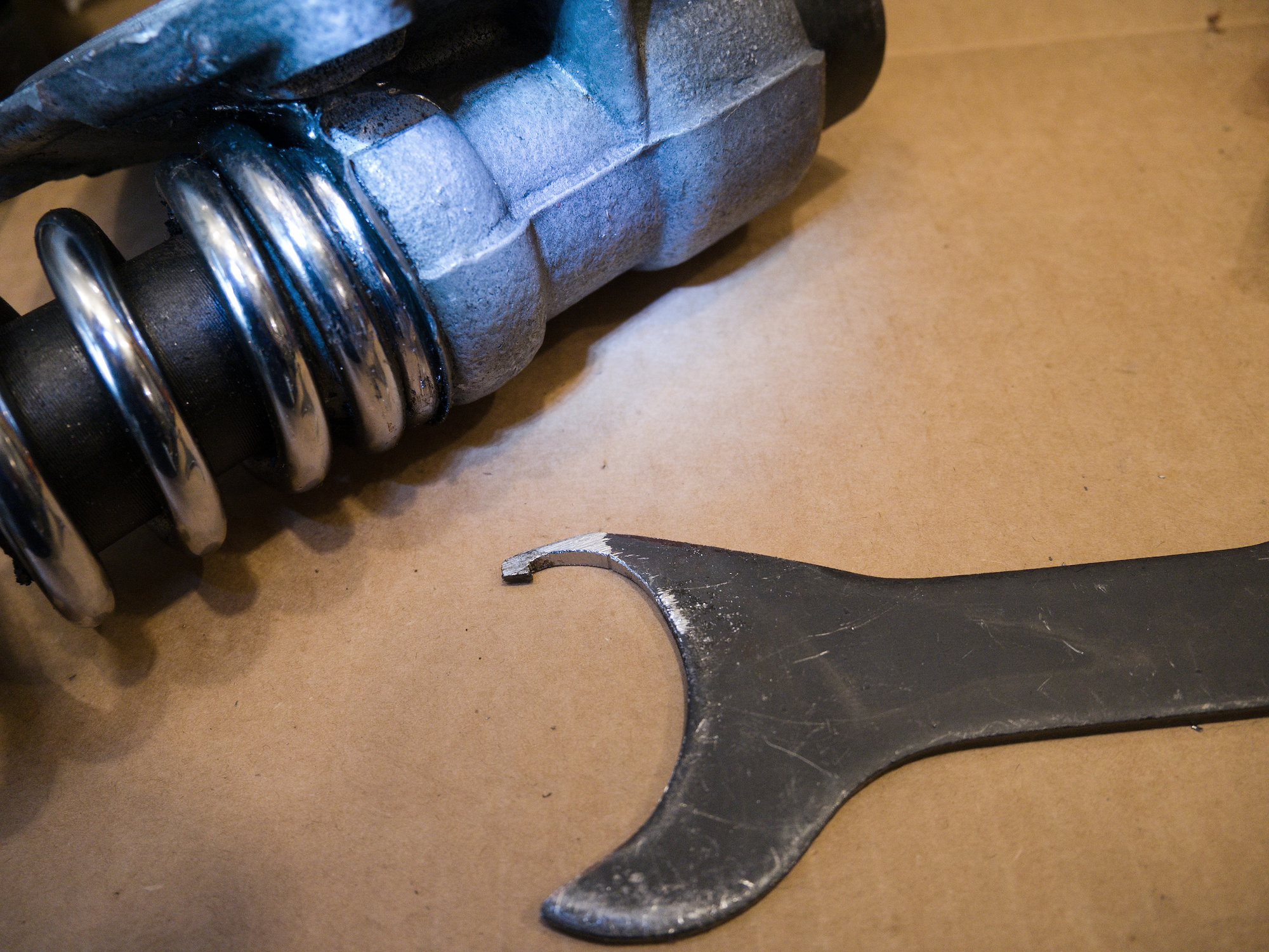
Level 4 of spring removal
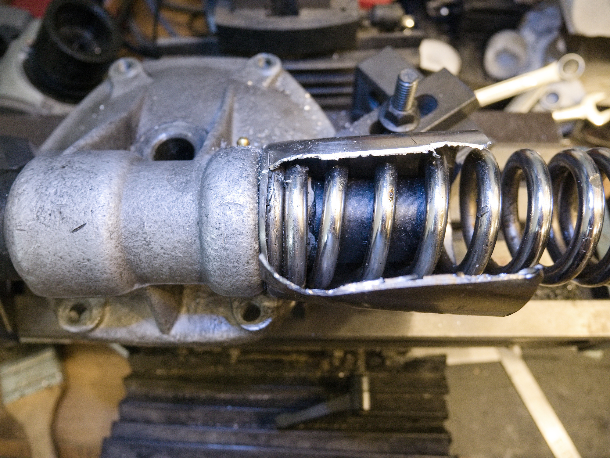
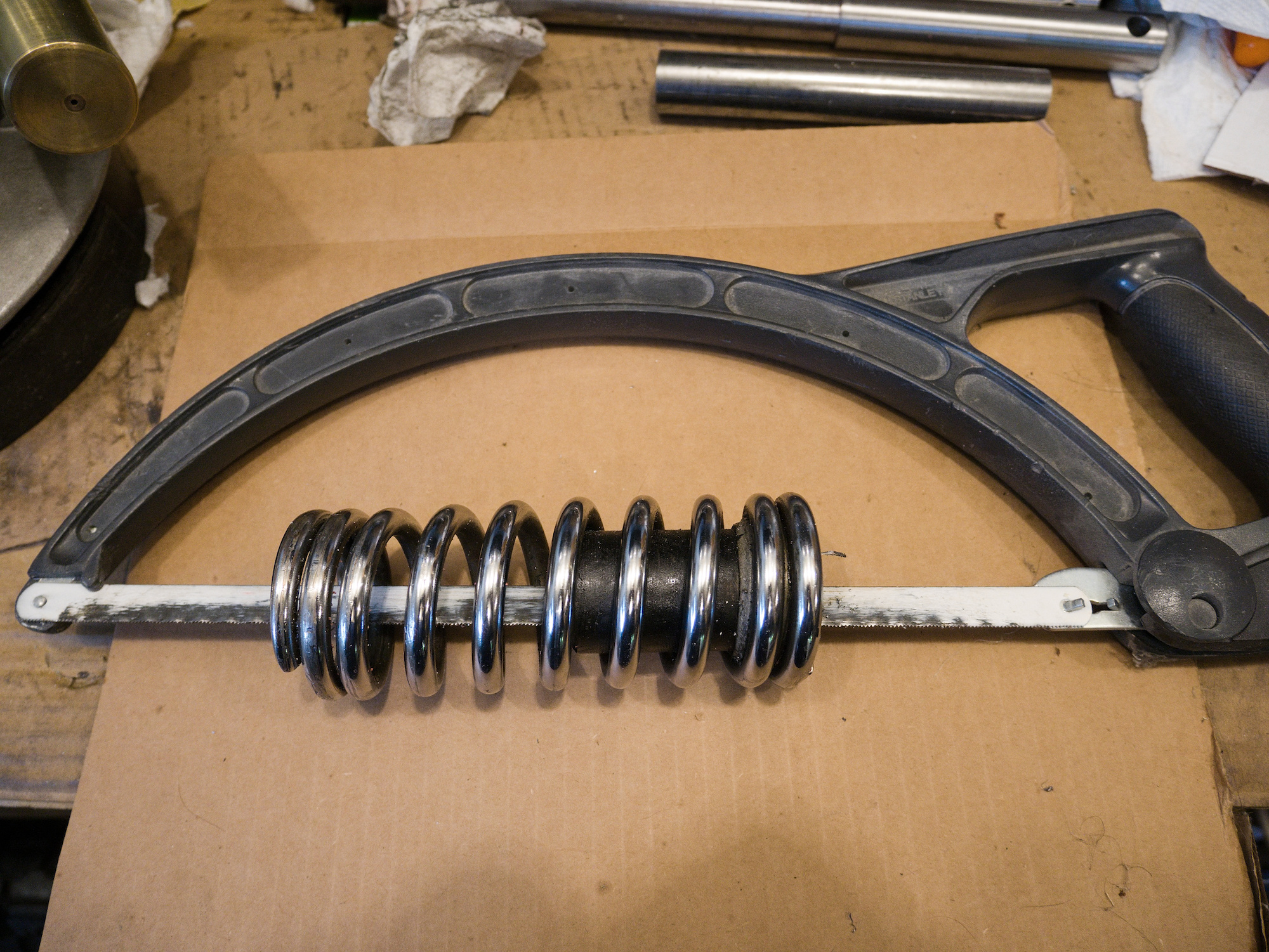
The cut.
I have only this perfectly matching spring, but enough of FD covers. The cover needs to go.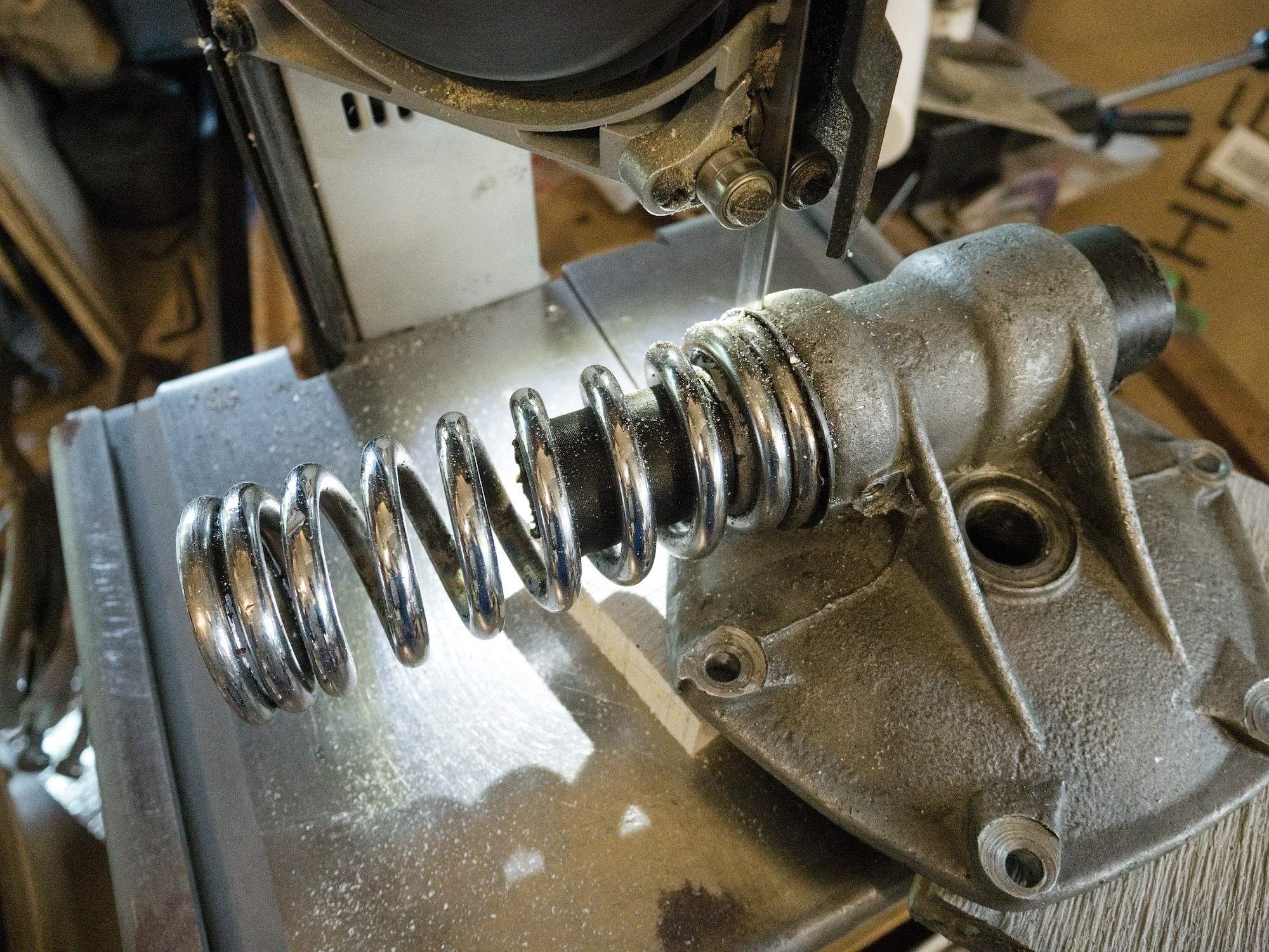
The spring tension cause the blade to break and get stuck halfway through the cut.
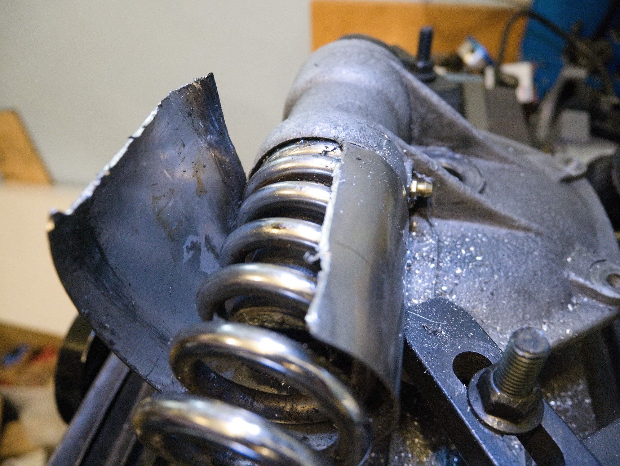
The spring is separated, but the guide for the suspension rod is still stuck.
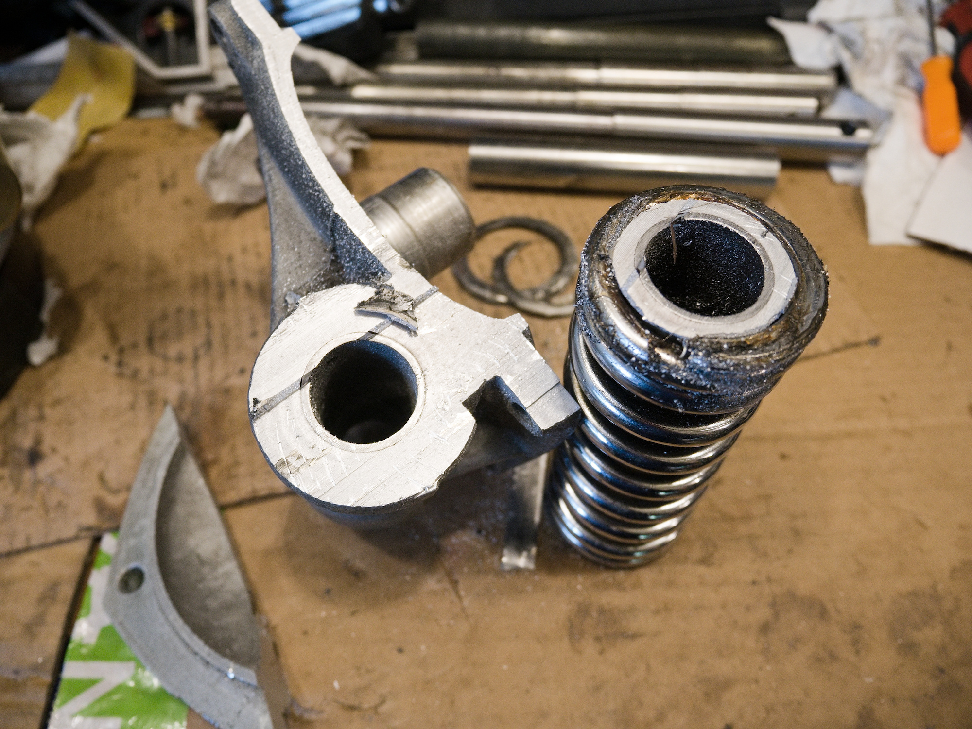
The plan is to make a saw cut from the inside.
The guide consists of two parts. The inner part can now be tapped out.
The outer part of the guide needs to be very carefully cut to not damage the spring.
Left side is the newly ordered spring, right side is the rescued spring.
-
Final Drive Rebuilt for CJ750 / M72 - Preparation
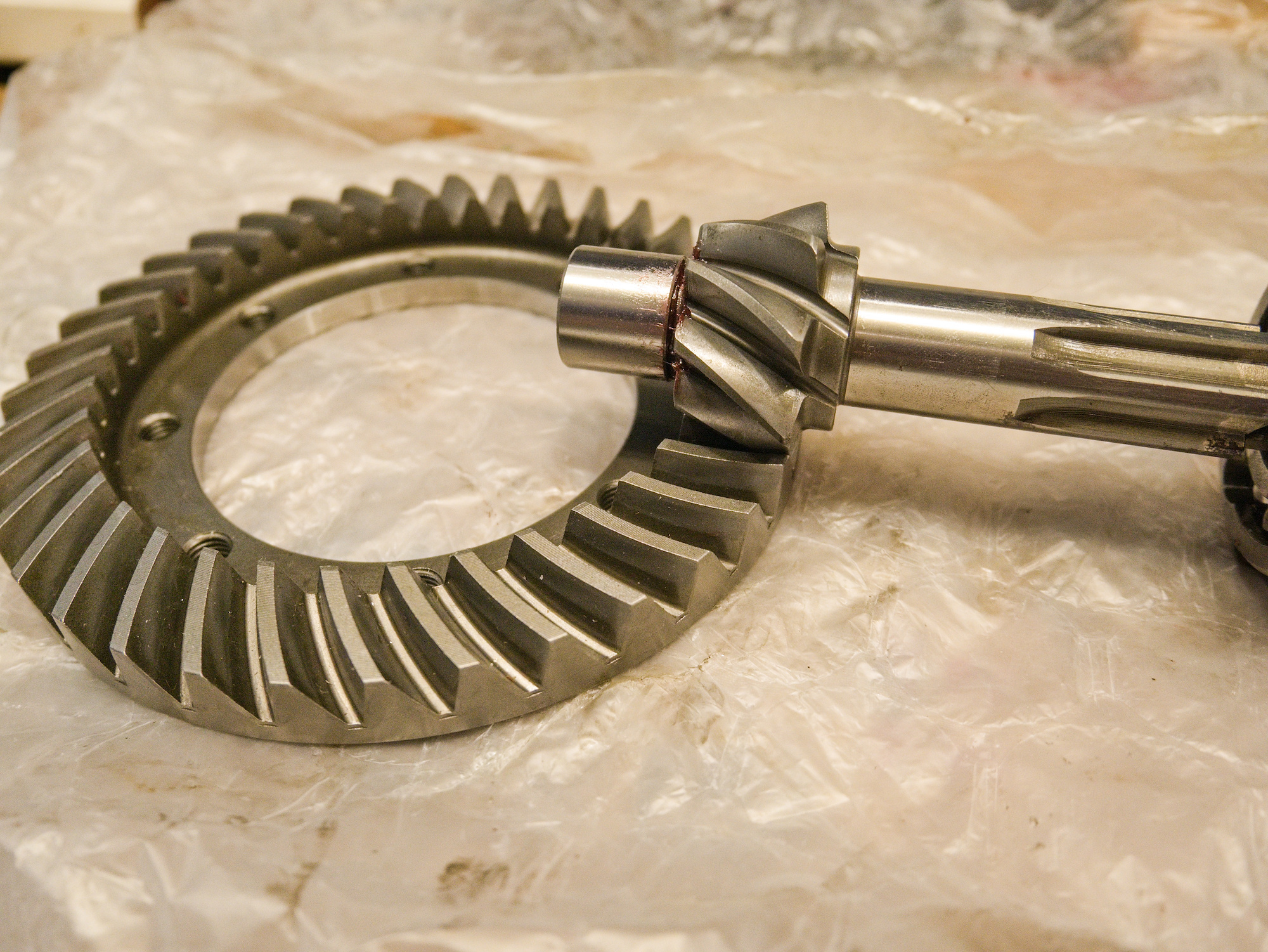
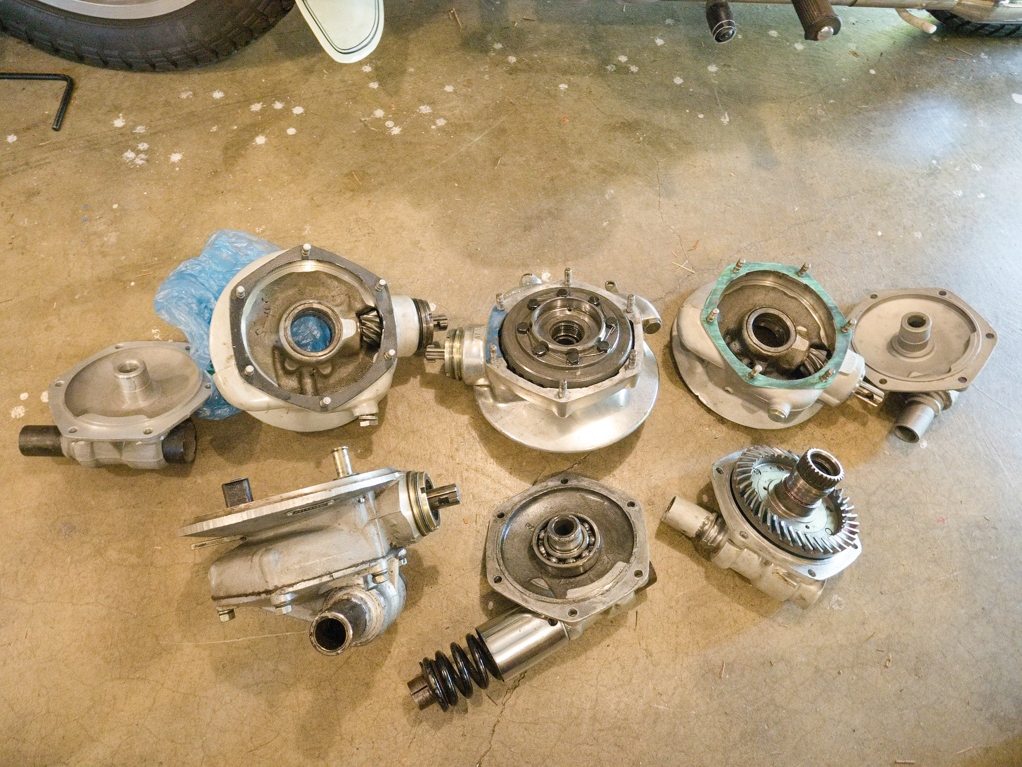
Not only have the CJ750 and M72 the same final drive (the thingy that connects the back wheel to the gearbox), but they also share the same Ring and Pinion gear of the Ural Motorcycle.
With the Ural 2019 and newer, final drives now running an European Ring and Pinion gear. Here I show you how to use those to upgrade your final drive (FD). So no more Russian or Chinese Junk!
See the Interview with Ural on youTube starting from 0:23 with details on the new gear set.
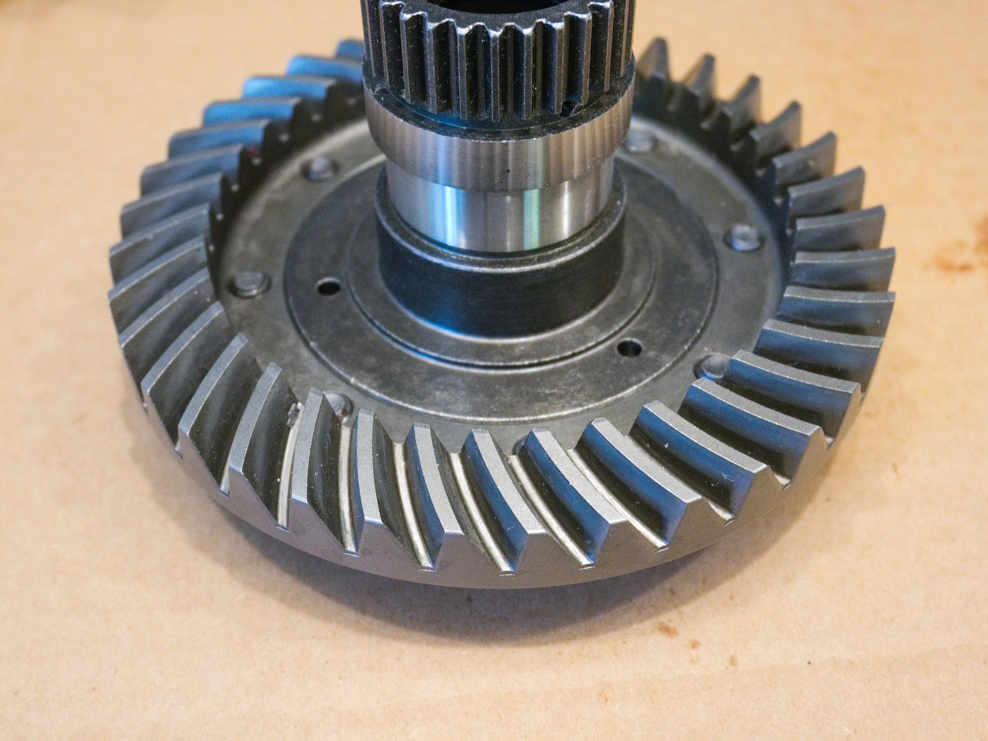
The European Ring and Pinion set is IMZ-8.128-05048 and has a 37/8 ratio.
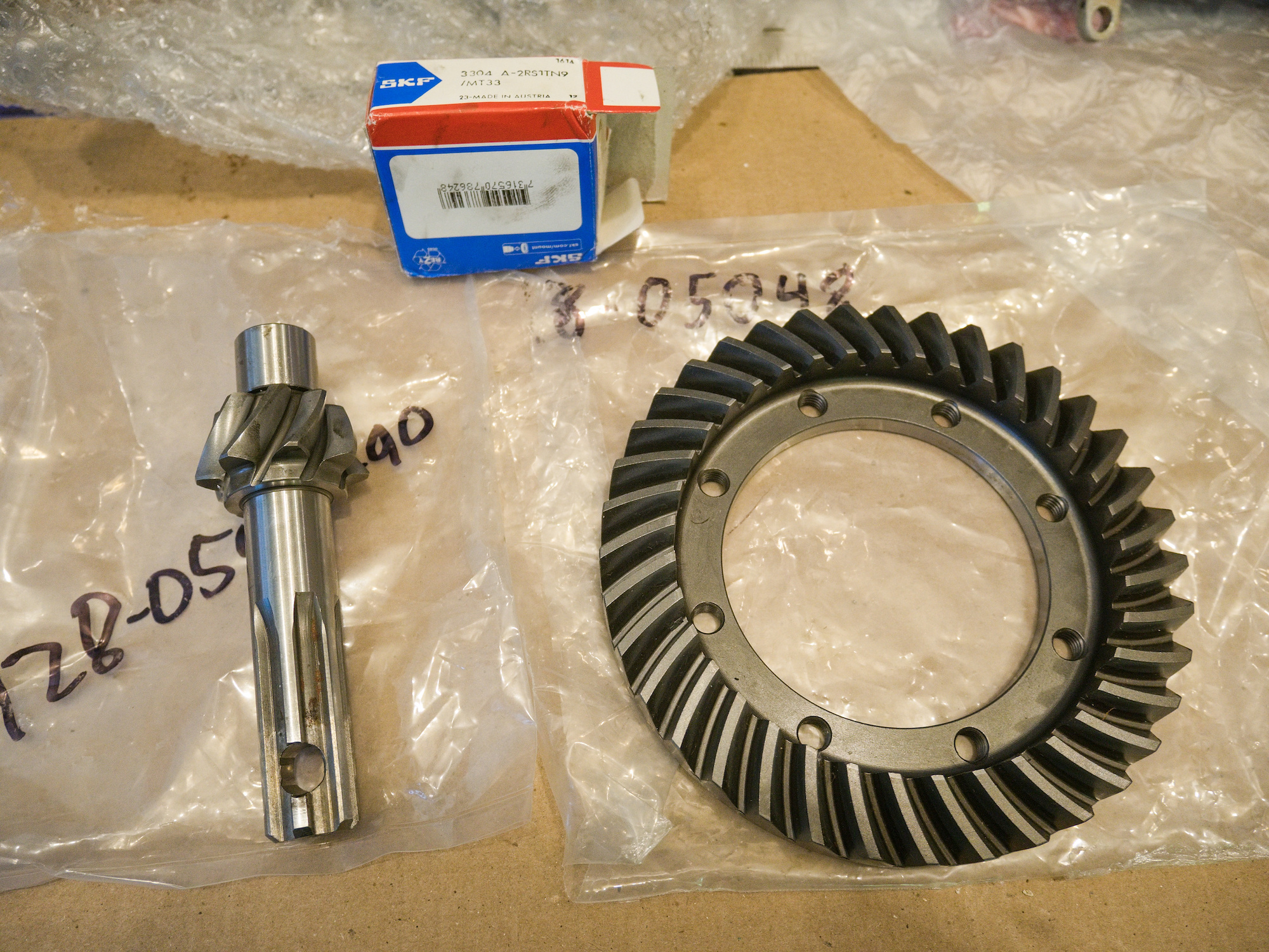
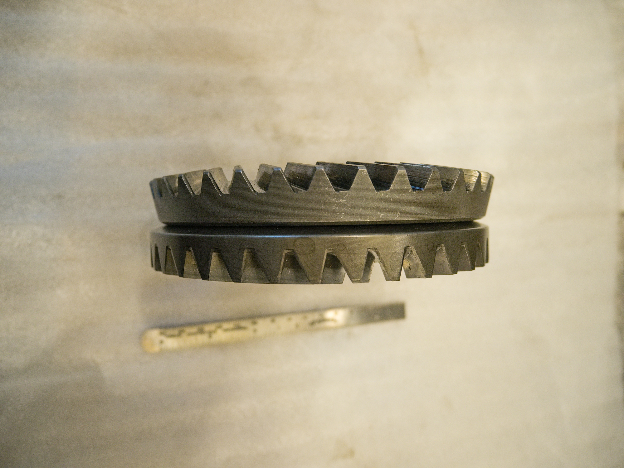
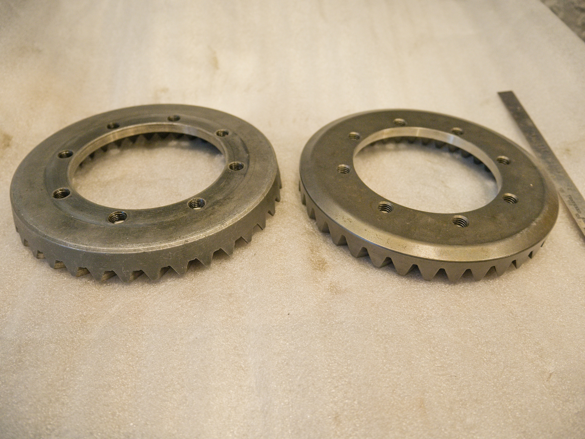
Left side is my old one. Right side is the new one from the Italian production. Italians are specialized in flat round things (Pizza).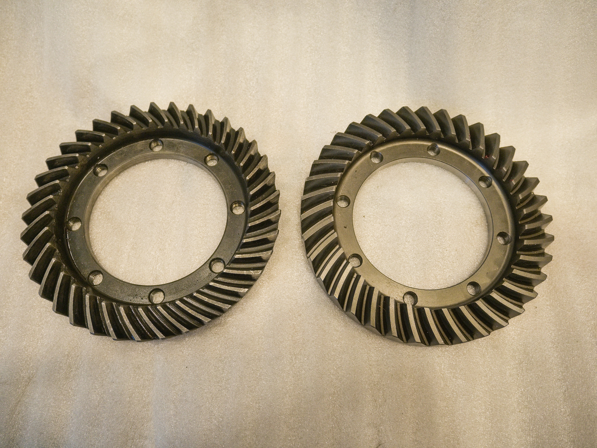
Bottom is the new one.
Bearings:
Ring bearing 6207c3
(35mm bore, 72mm OD, 17mm width)
Pinion bearing 3304
Bearings can have different properties. For example:
3304 A-2Z/C3
Angular contact ball bearings, double row
2Z: Shield on both sides (Z is for metal shield)
C3: Internal clearance greater than Normal3304 A-2RS1
Angular contact ball bearings, double row
2RS1: Contact seal, NBR, on both sides (RS is for rubber seal)C2: Clearance less than normal clearance
C1: Clearance less than C2 clearance
C3: Clearance more than normal clearance
C4: Clearance more than C3 clearance
C5: Clearance more than C4 clearance3304 A-TN9
TN9: Glass fibre reinforced PA66 cage, rolling element centered
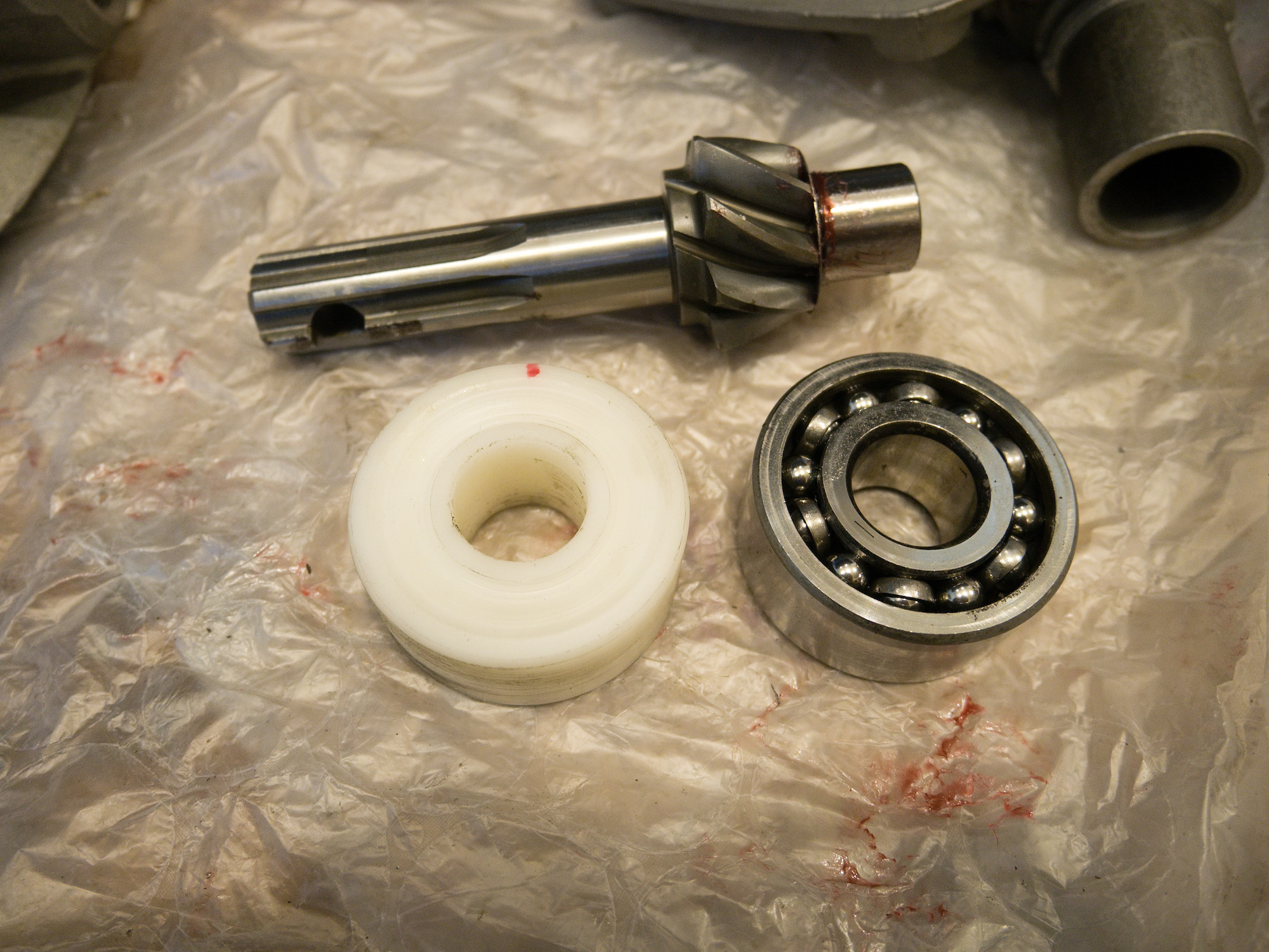
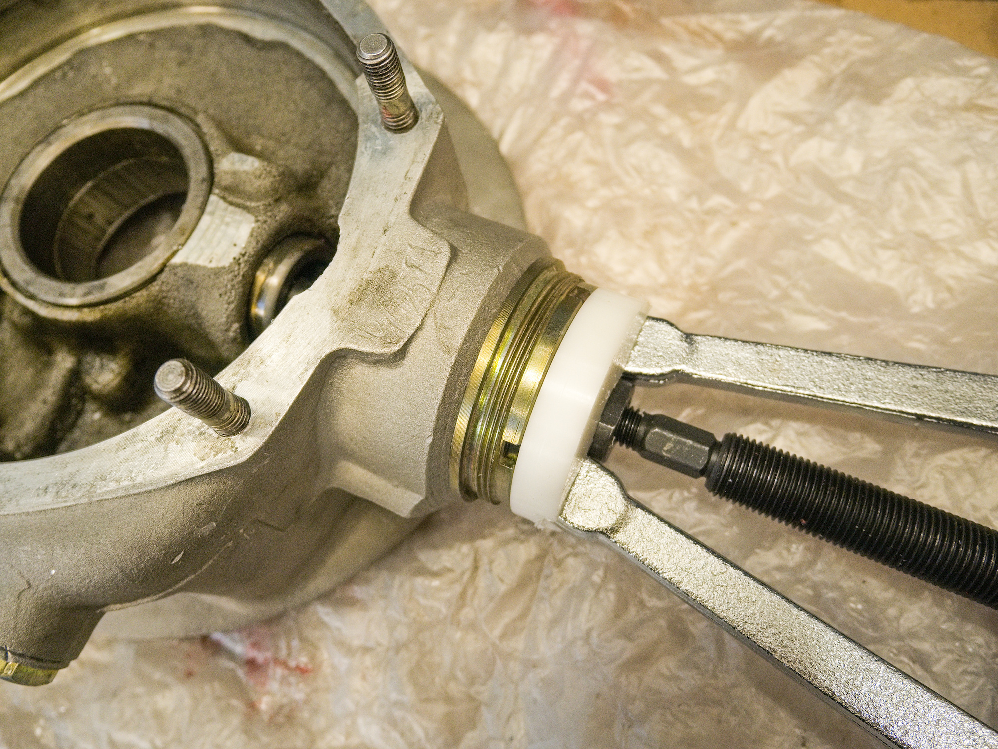
The 3304 gets pressed on later to the pinion gear shaft. For the contact pattern, a plastic guide with the same dimensions as the bearing is used to make it easier to move the gear in and out of the casing.
The following places are a good source if you want to start with new parts. I have used them all and they provided exceptional service.
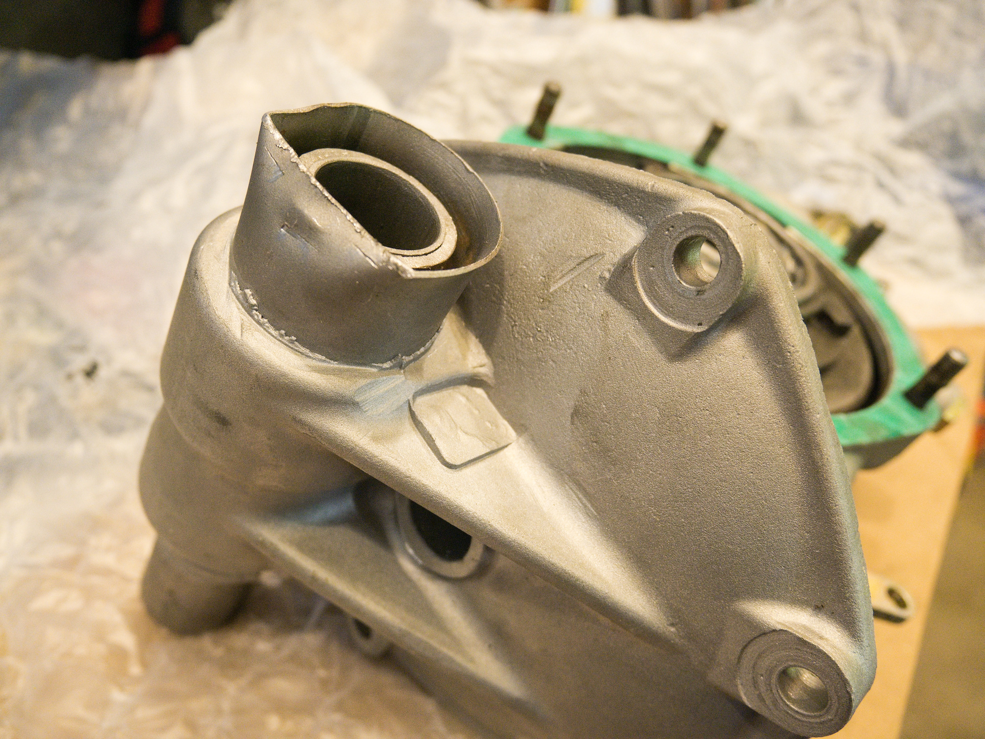
Please be aware that shipping damage can happen despite the best efforts of the packaging. Like this bend, which is a quick fix. Project on!
Note: The M72 has only one stabilization fin on the housing, while the CJ750 has two as seen in this picture to make the housing more stable. But in general parts are exchangeable.
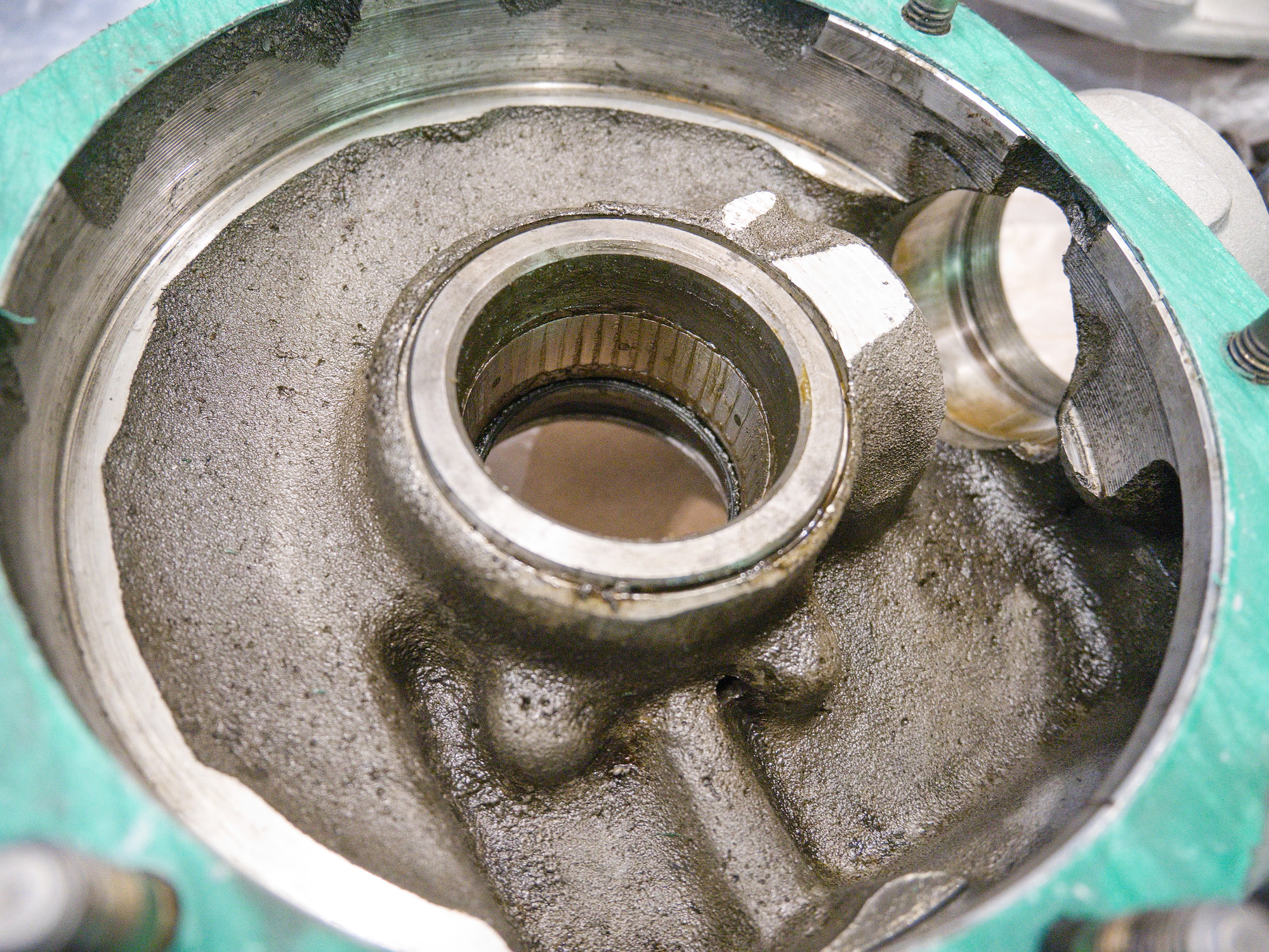
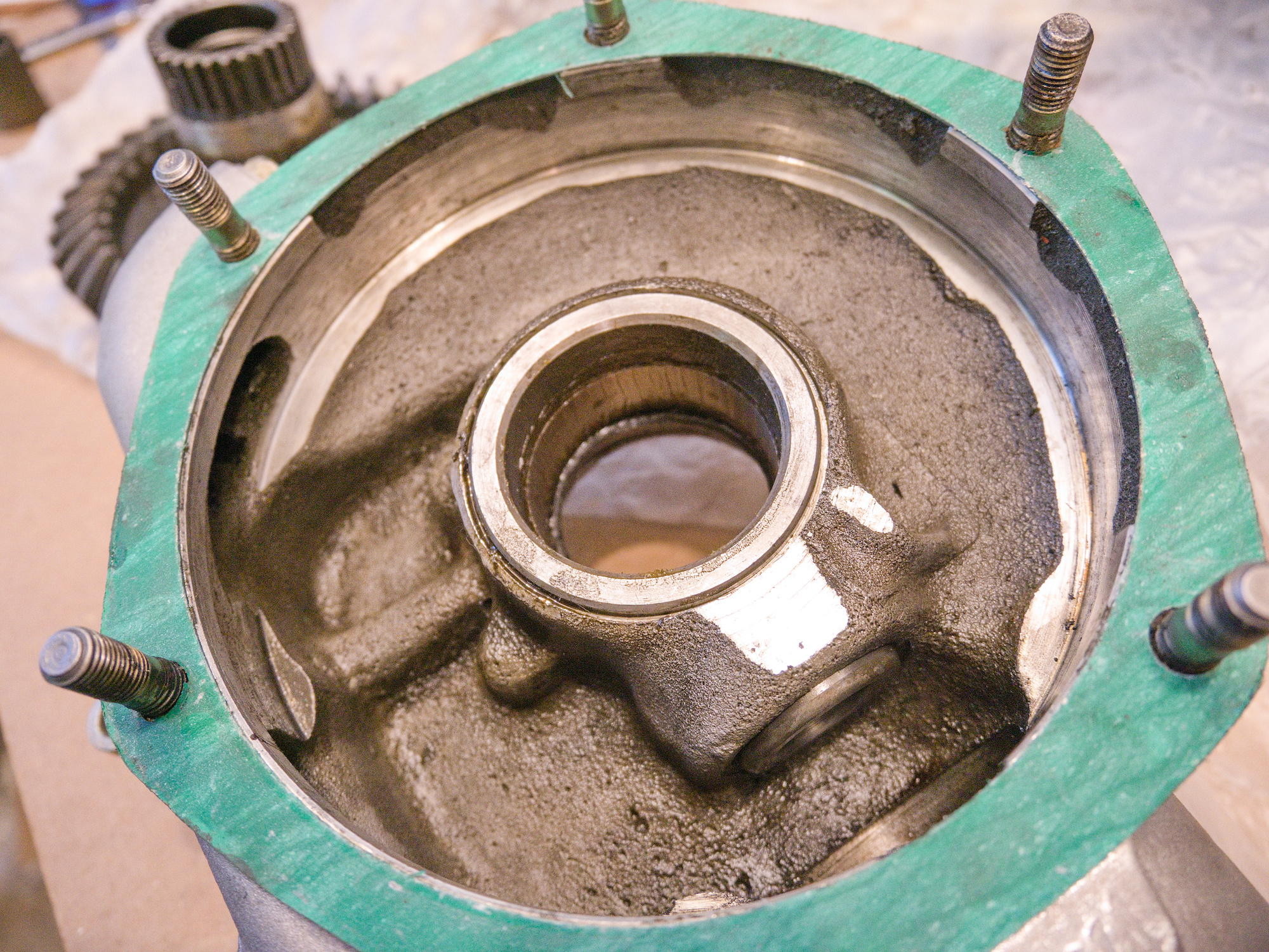
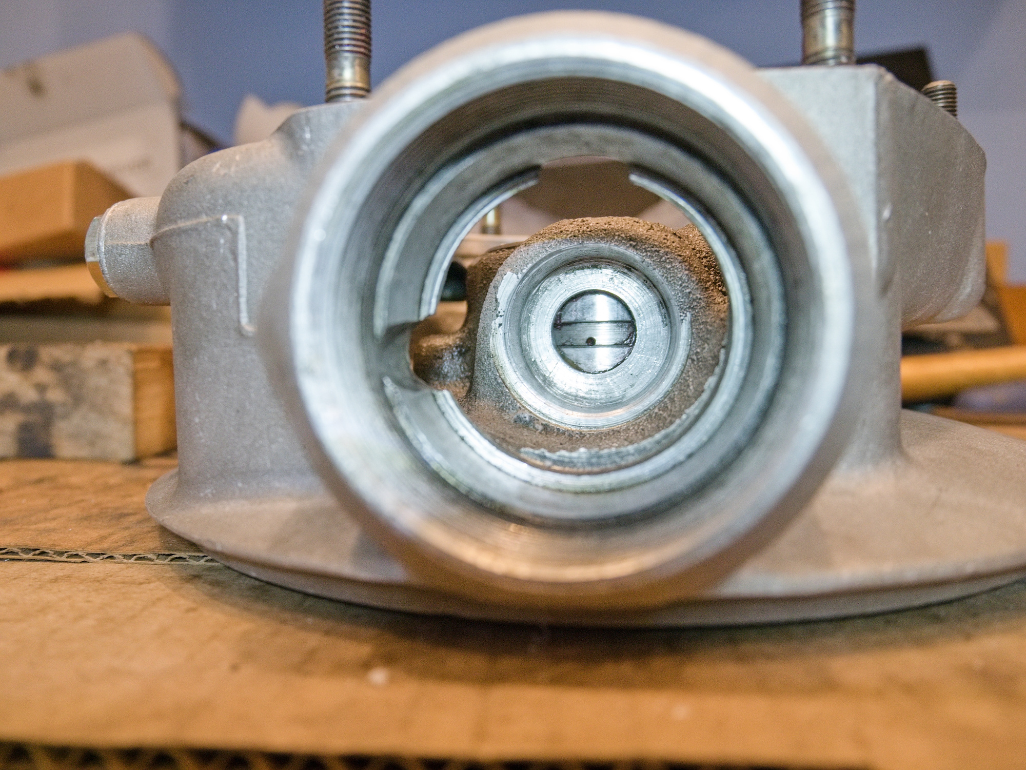
Inspect all parts, and make sure all oil channels are clear.
The oil drain from the main seal to the bottom is most important. It prevents oil contaminating the break shoes.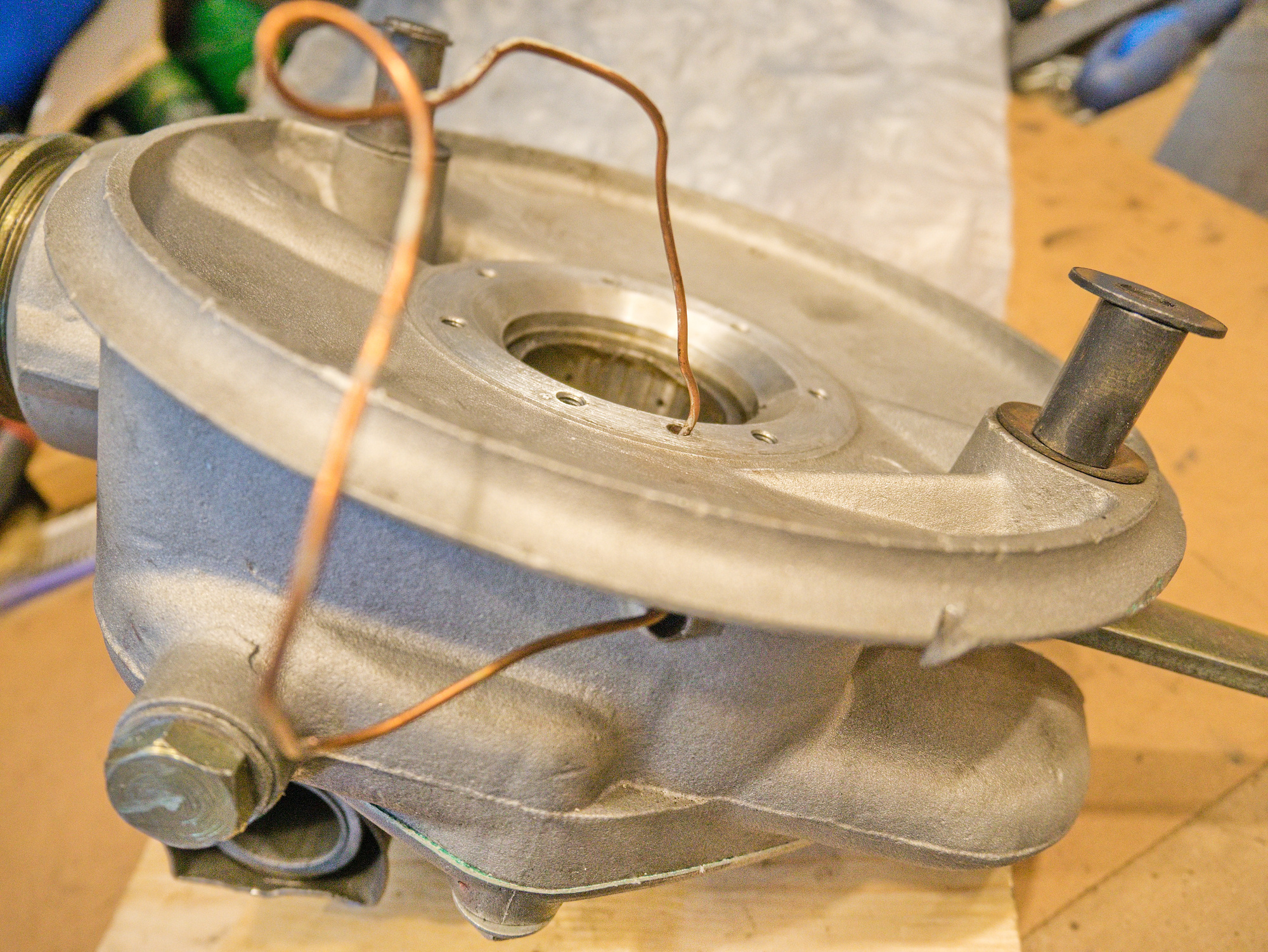
FDs consumables. My collection.
Pinion inner bearing
The pinion inner bearing is normally 20x32x20, but with the new pinion it needs to be 20x32x16. This is a NKI20/16 Needle Roller Bearing.
The existing pinion gear race in the FD needs to be removed. A simple task using a Blind Hole Puller (from a Blind Hole Collet Bearing Race and Seal Puller Extractor Kit in case you are looking for such puller), and a piece of protecting plastic.
Make sure the tiny hole to the main bearing is also clear.
-
Benzinkanisterhalter, Teil 2, das Zusammenbauen
Projekt Benzinkanisterhalter, Teil 2, das Zusammenbauen:
Alle Teile werden jetzt zusammengeschweißt. Die Rundbögen sind von einem Kranz aus einer Bremse, die in 4 Teile geschnitten worden ist:


Die Halterung wird mit einem Halter befestigt, der an die Innenseite des Beiwagens angepasst ist:
-
Benzinkanisterhalter, Teil 3, das Montieren
Benzinkanisterhalter, Teil 3, das Montieren
Der Halter für die Halterung wird an der Innenseite des Beiwagens montiert. Der Vorteil dieser Halterung gegenüber einfachen Schrauben im Blech ist in der Kraftverteilung. Das Blech verformt sich bei großer Last nicht: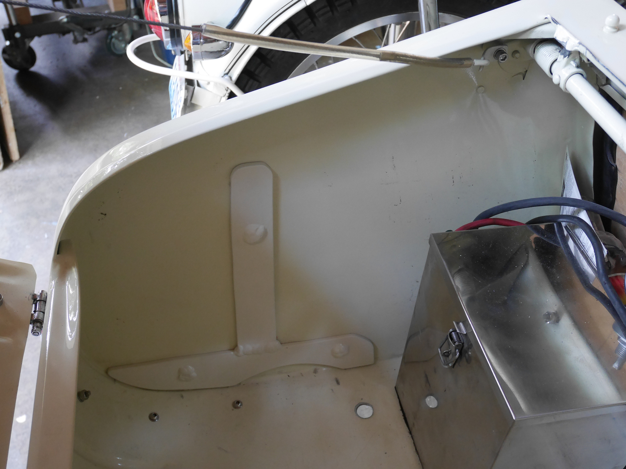
Der Bügel wird mit einer Feder gespannt und hält den Benzinkanister.
Das Auslaufrohr wird auf die schwarze Halterung gesteckt.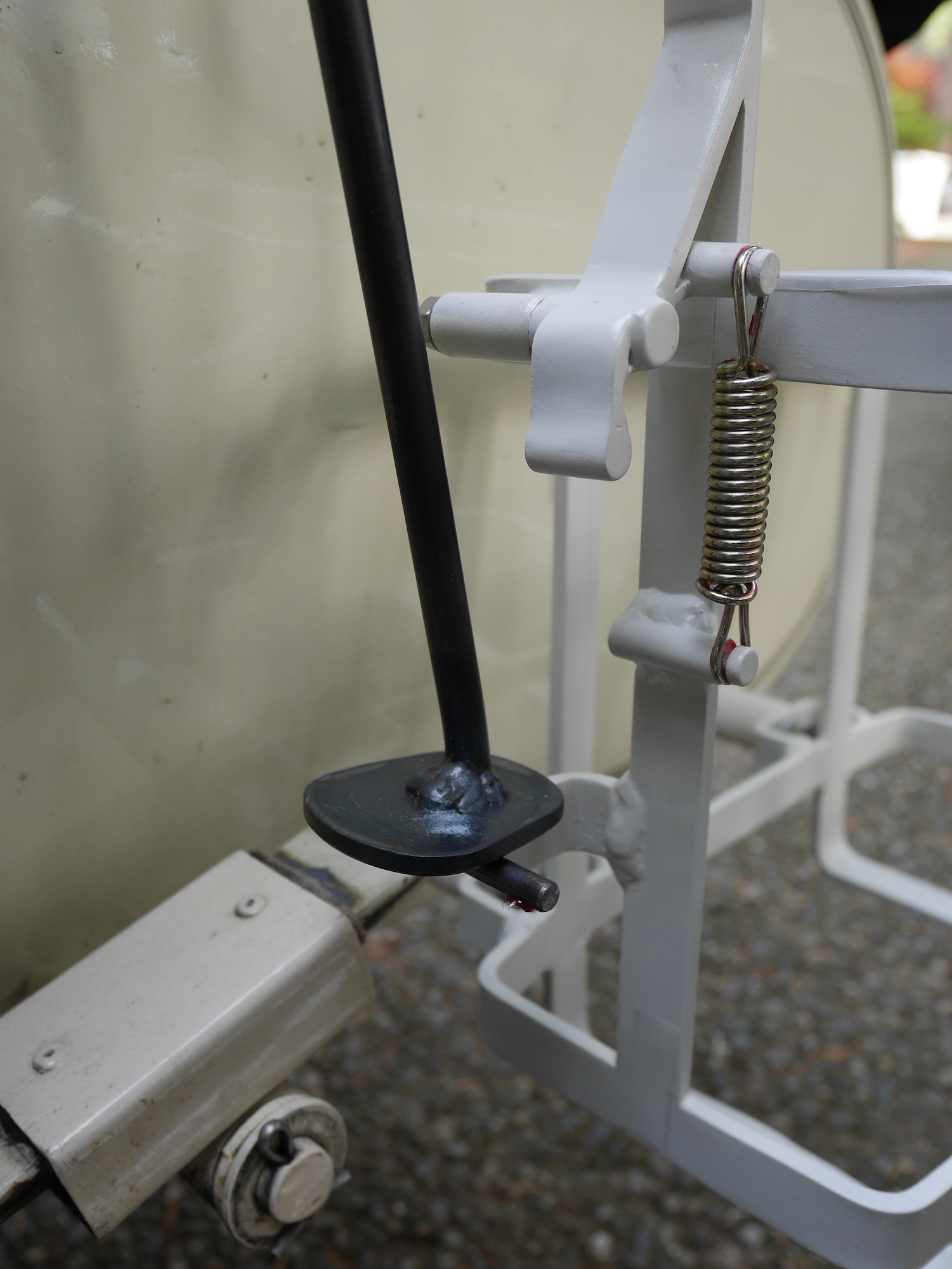
Fertig montierter Benzinkanisterhalter:
