-
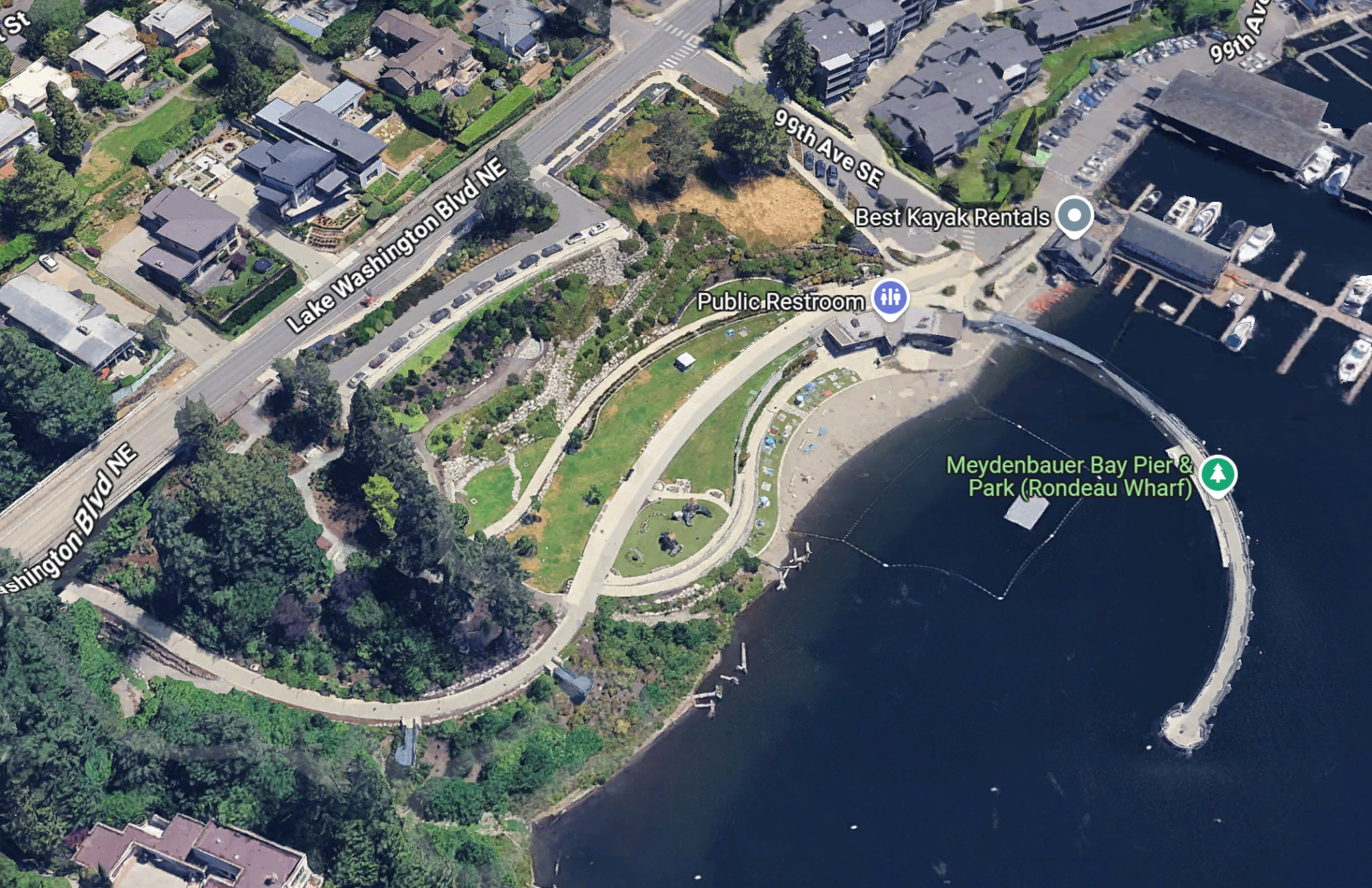
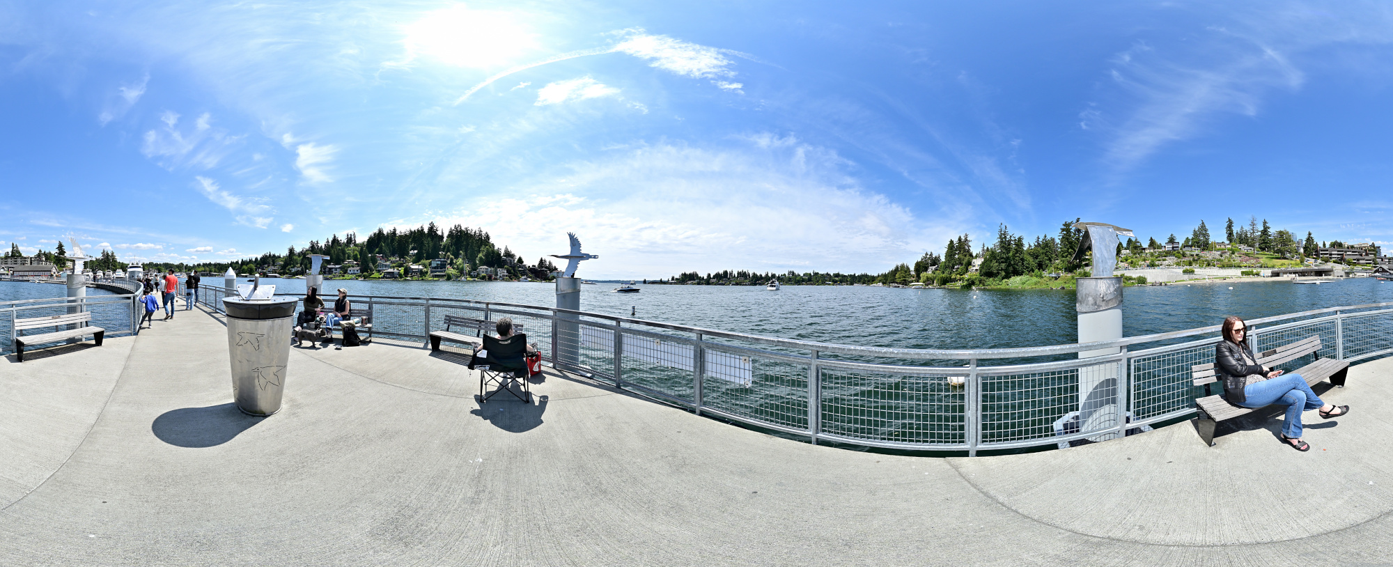
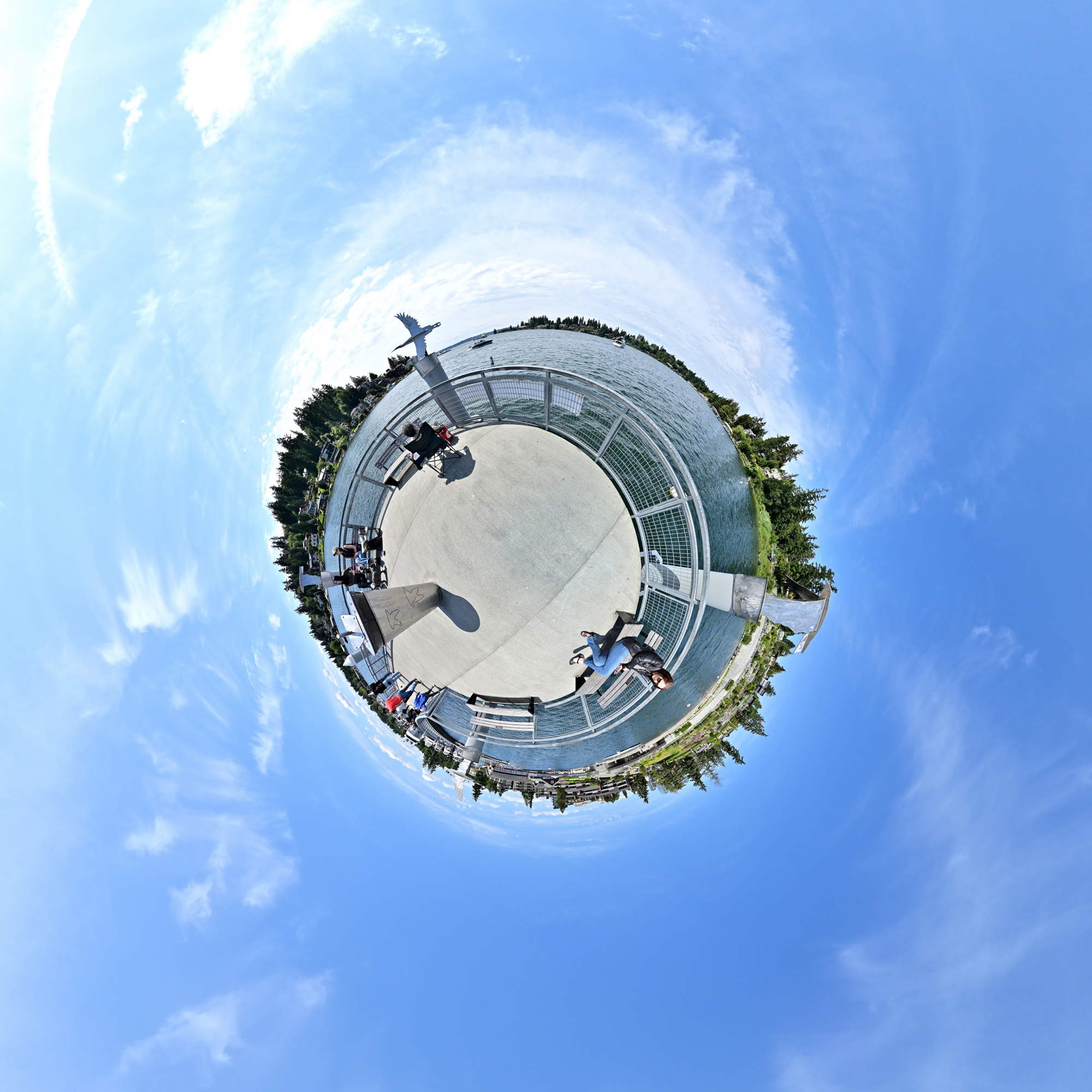
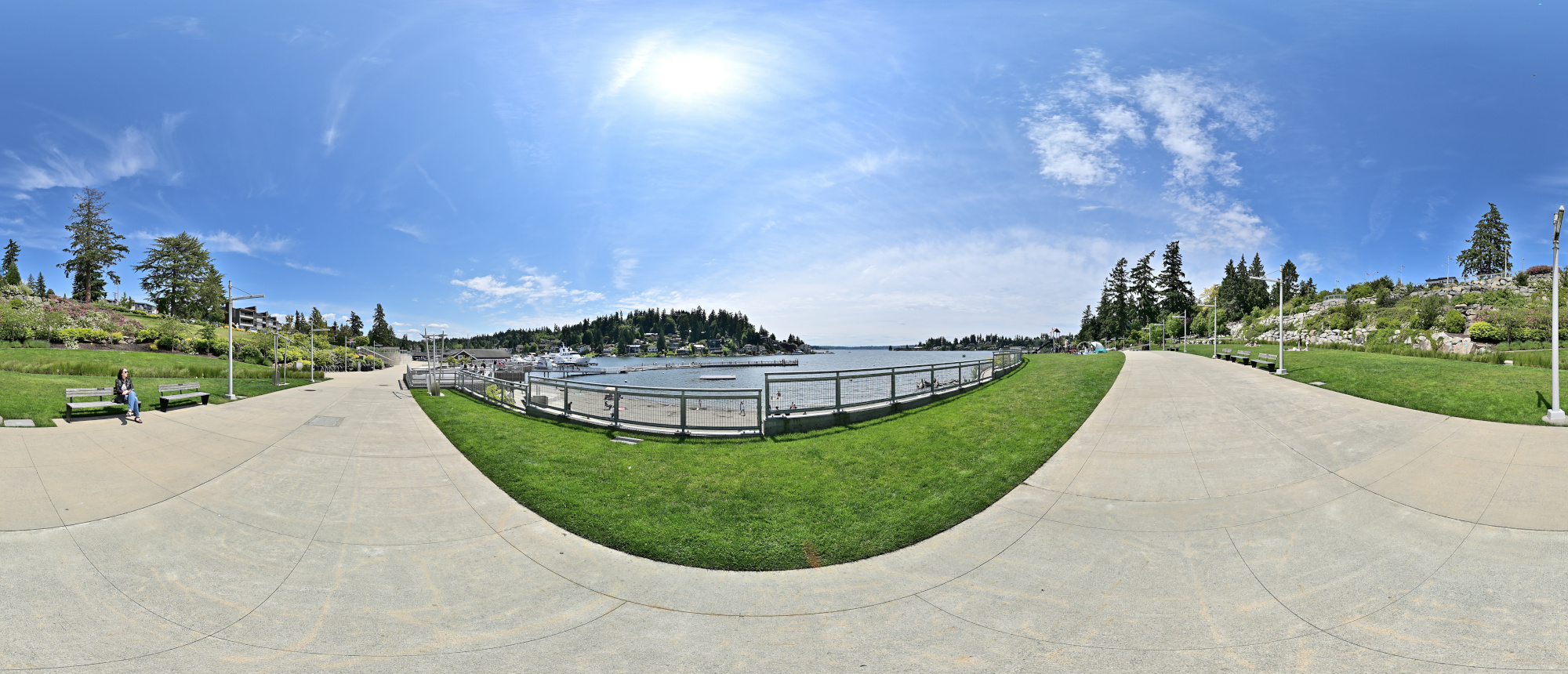
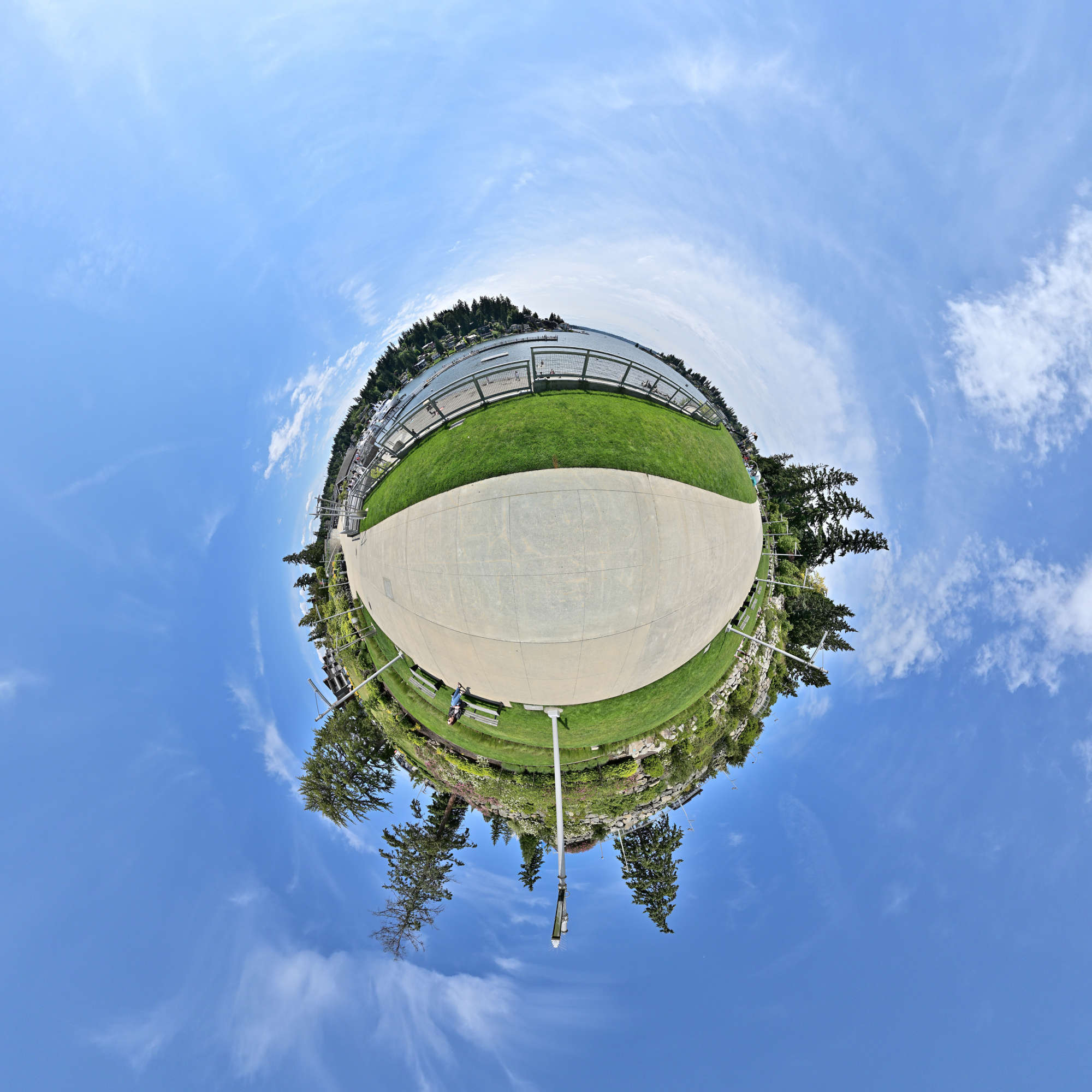
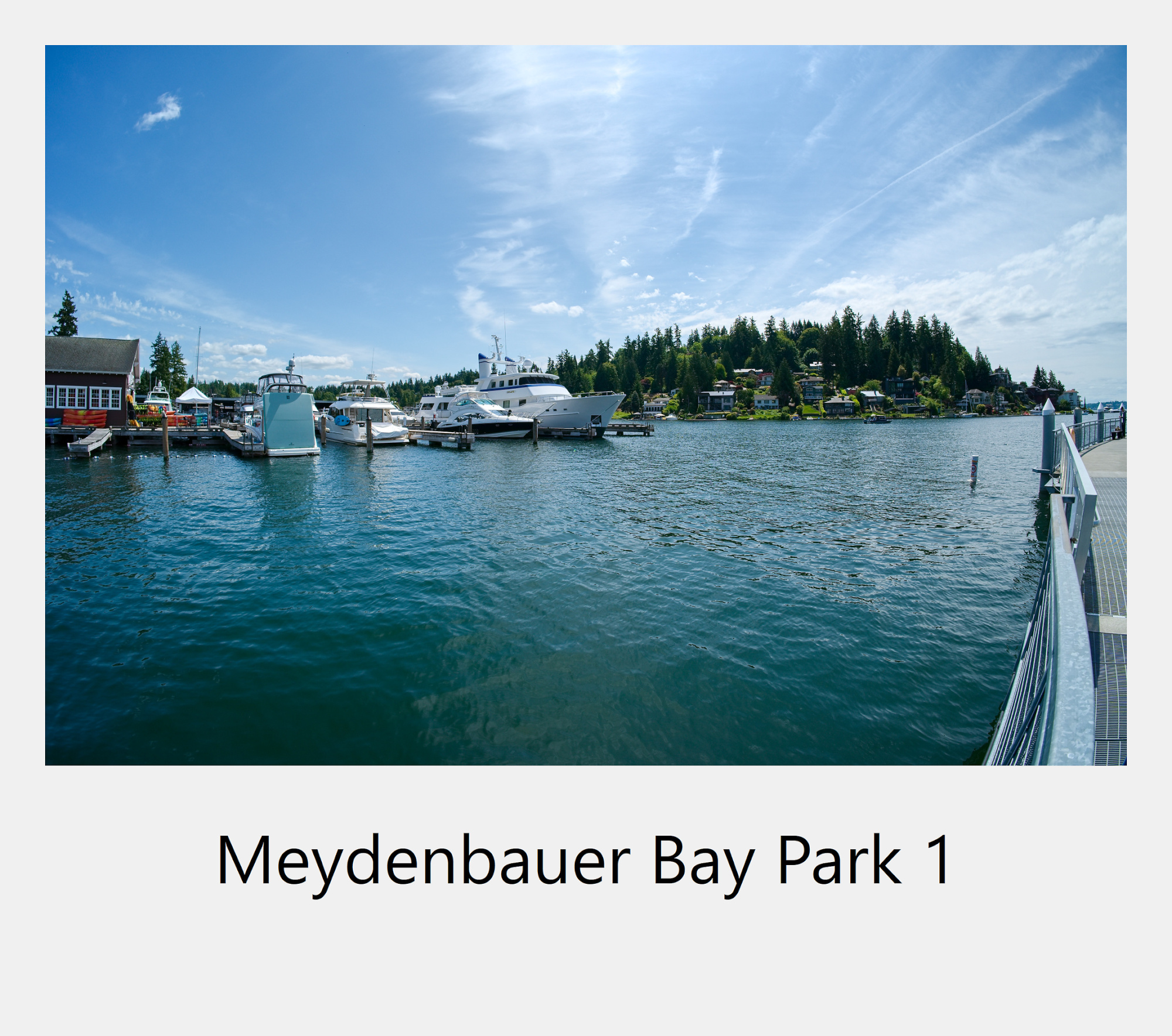
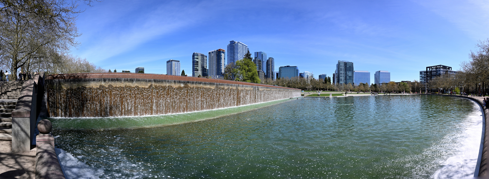
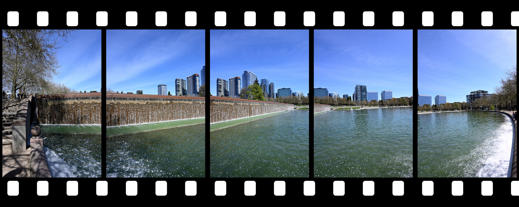
Meydenbauer Bay Park
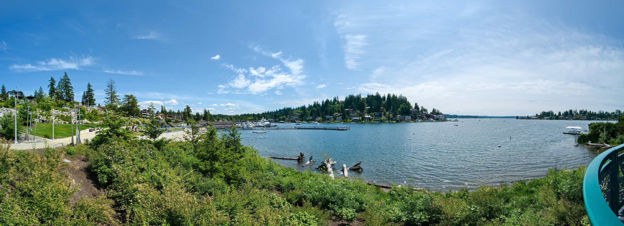
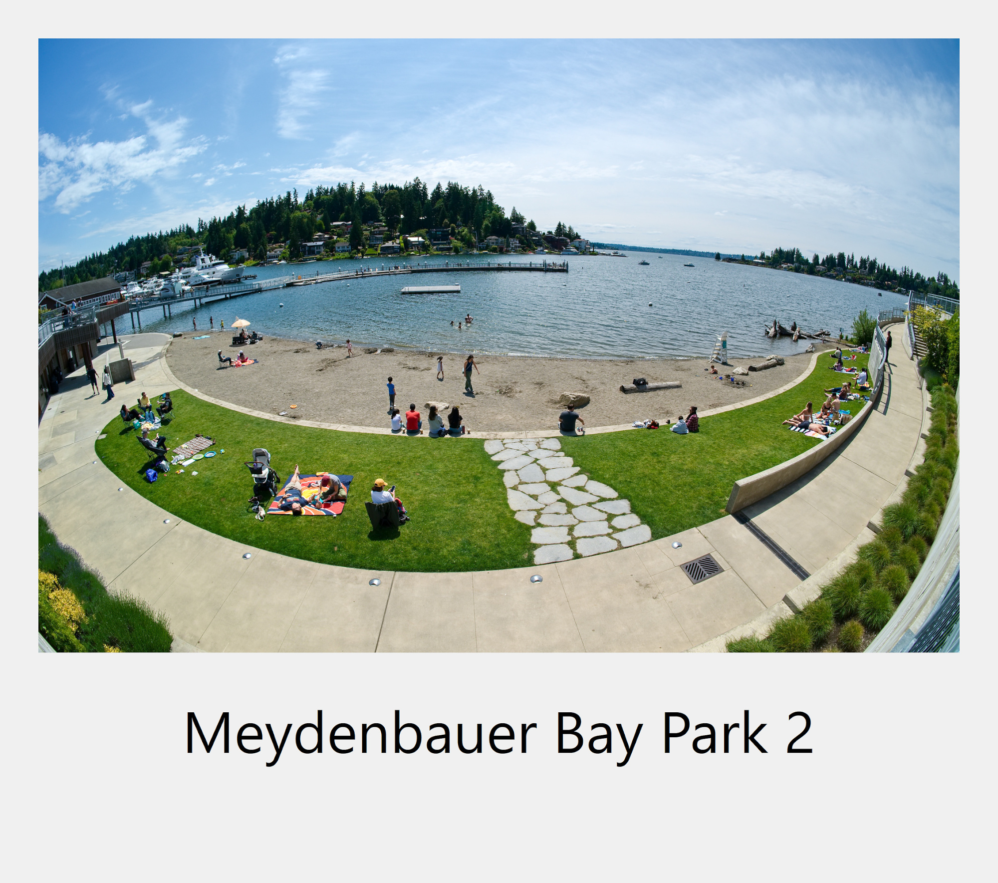
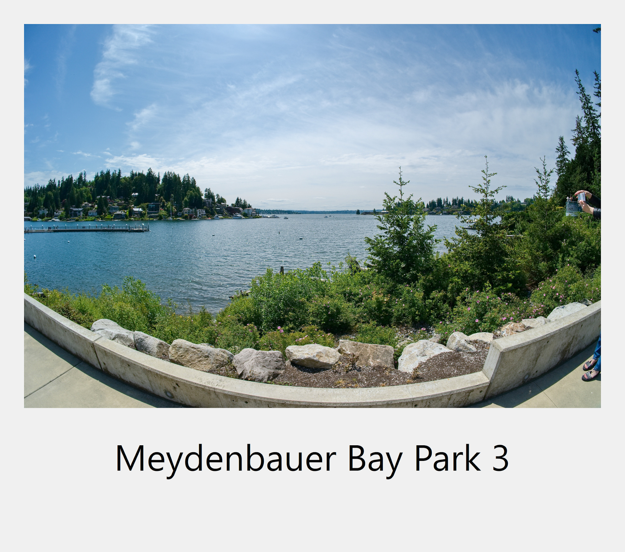
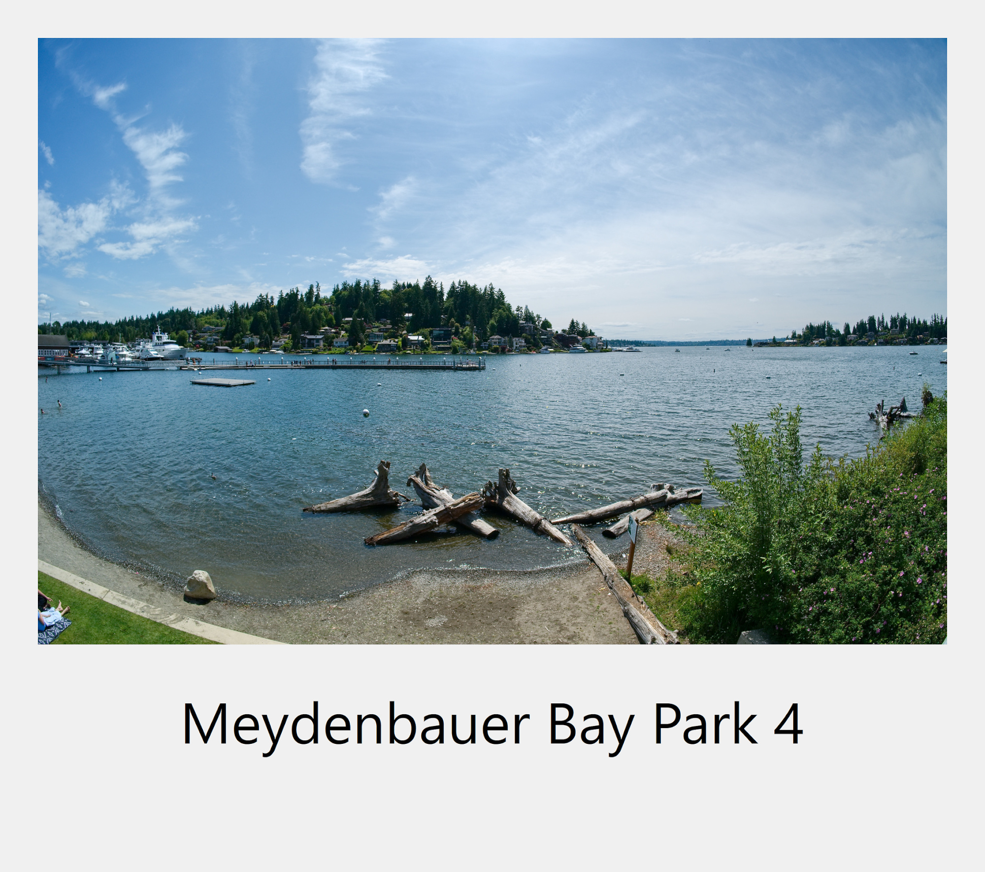
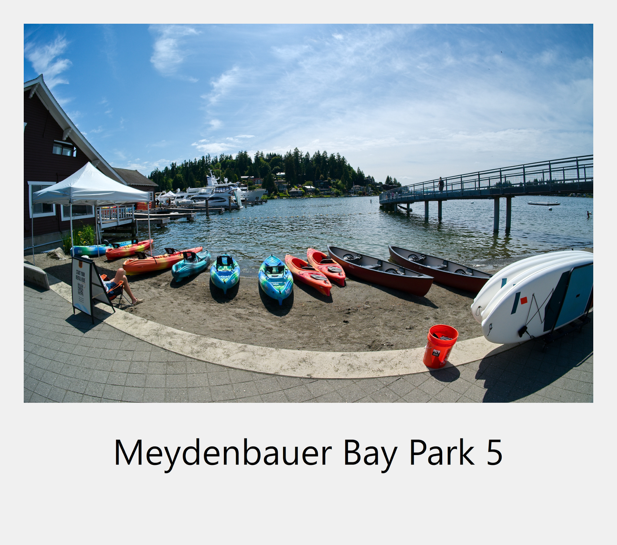
Sunny Sunday afternoon at the Meydenbauer Bay Park.
Interactive Panorama Meydenbauer Bay Park 1
1/1000s f/5,6 ISO 100/21° f=7,5mm
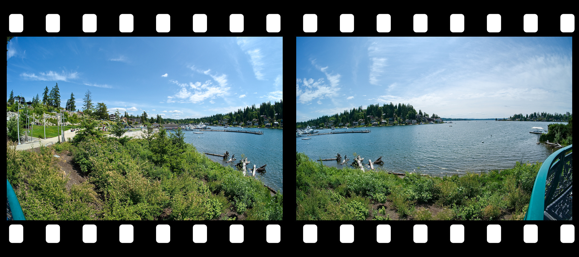
Interactive Panorama Meydenbauer Bay Park 2
1/1000s f/5,6 ISO 100/21° f=7,5mm
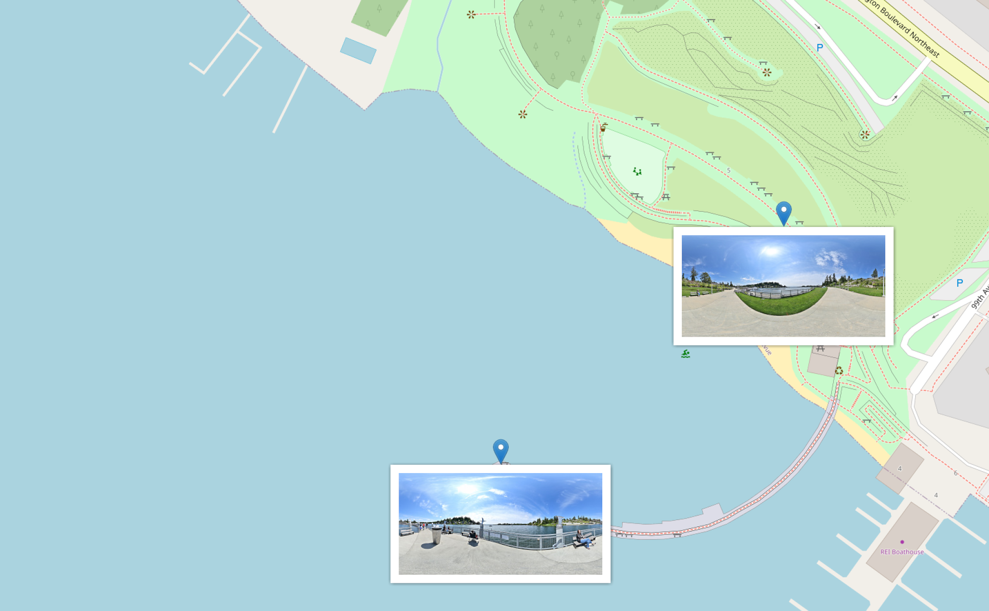
cPicture map
1/1000s f/5,6 ISO 100/21° f=7,5mm
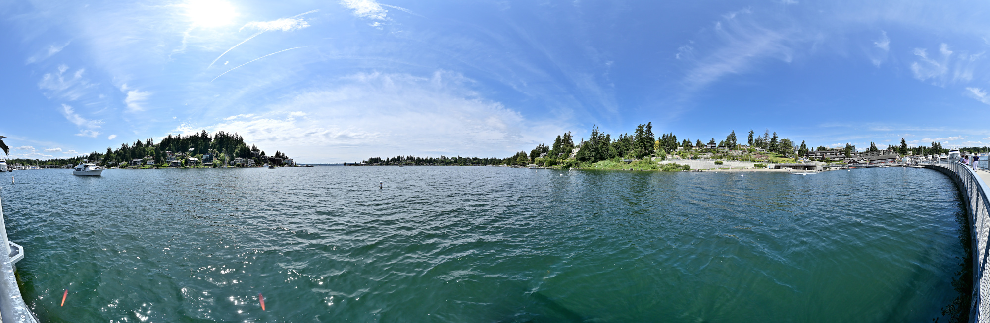
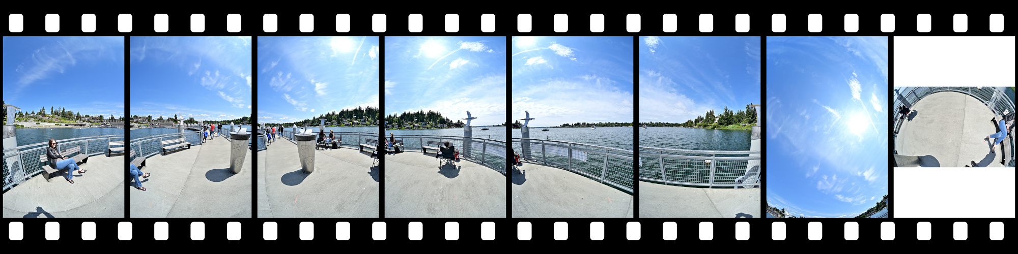
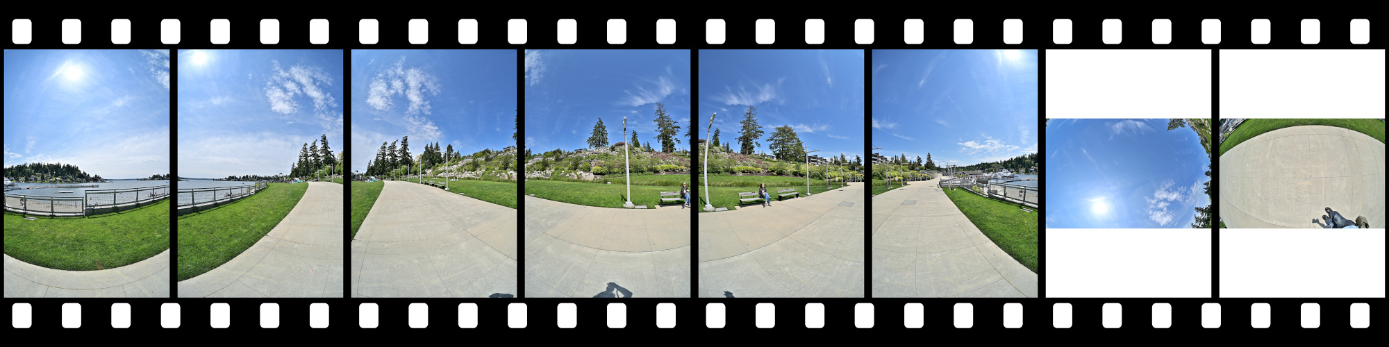
This panorama was captured from 7 vantage points on the observation platform.
Almost like The Tower Panorama.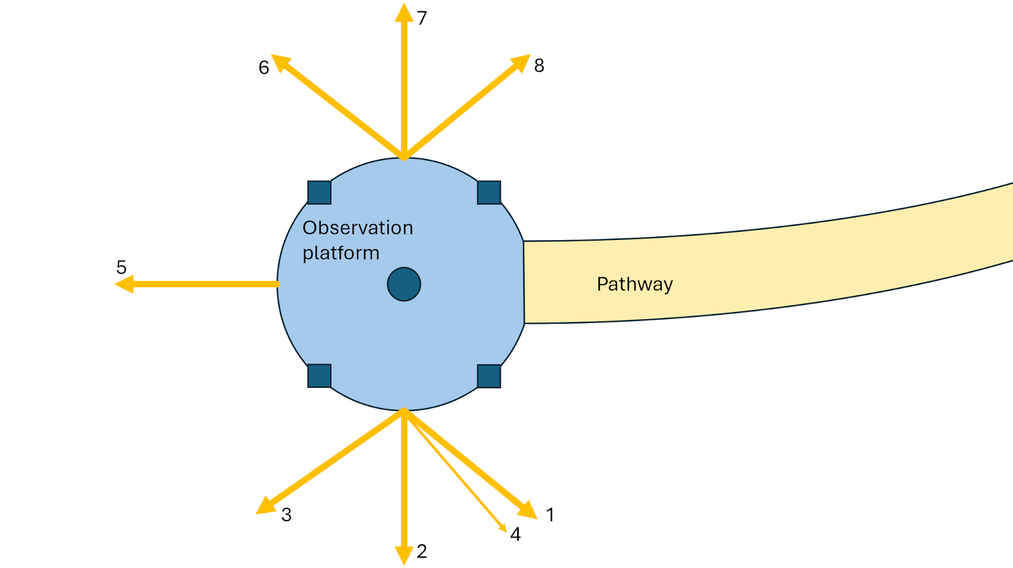
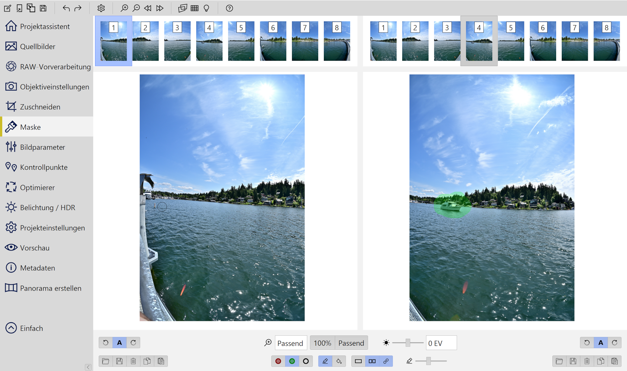
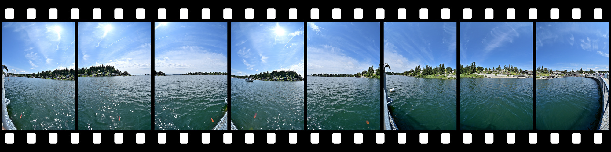
A total of eight images were used to create the panorama. One additional shot (#4) was taken moments later to capture a boat that had just entered the scene. Since this image was slightly out of alignment, it was registered to the first frame using control points and selectively masked to seamlessly integrate the boat into the final composition.
1/1000s f/5,6 ISO 100/21° f=7,5mm
-
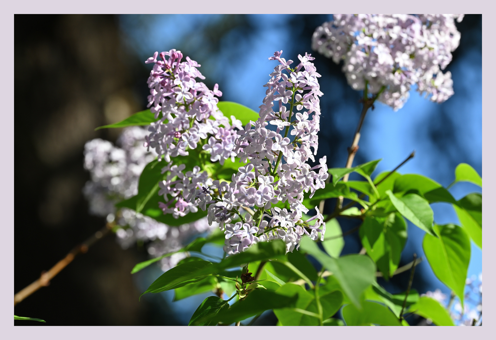
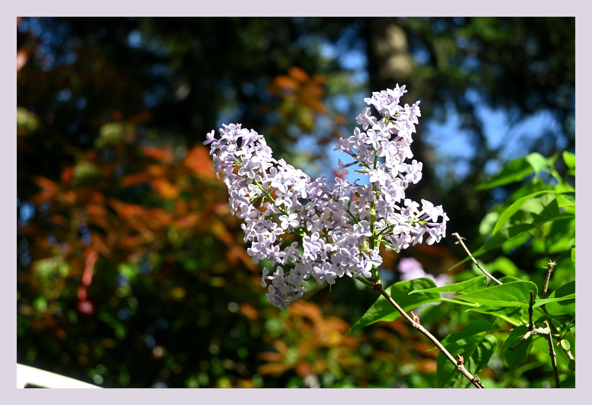
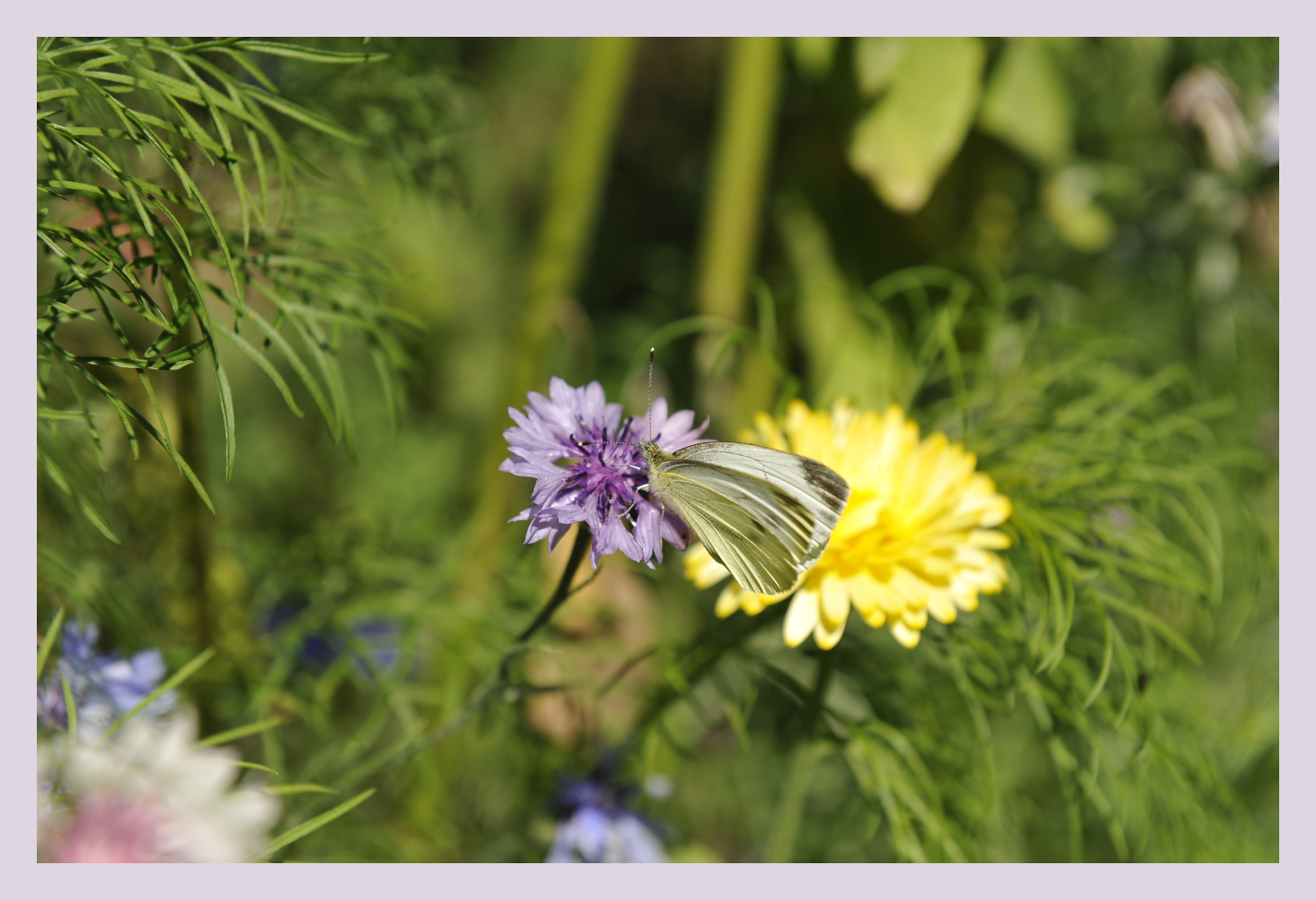
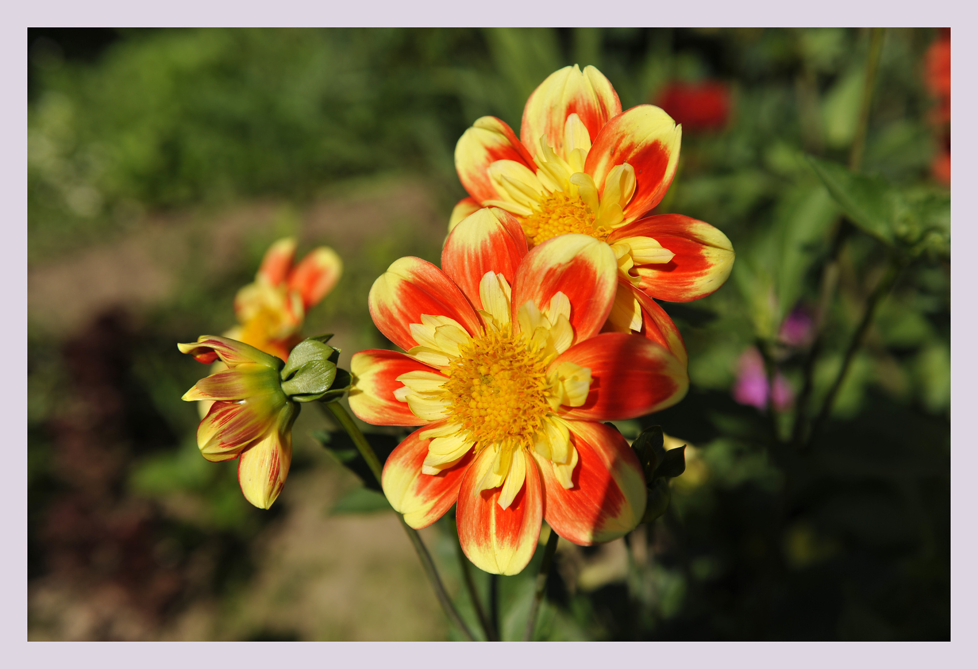
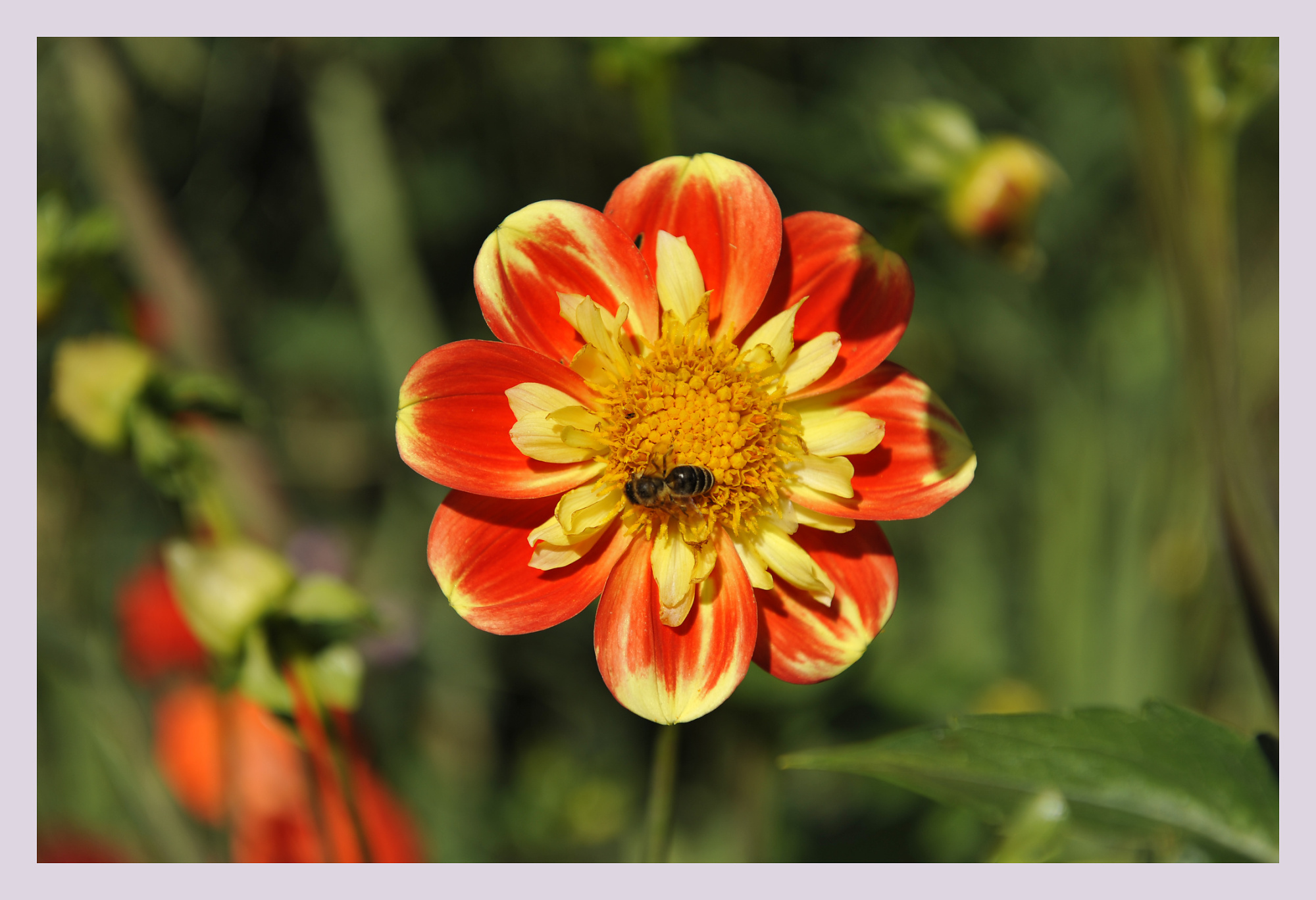
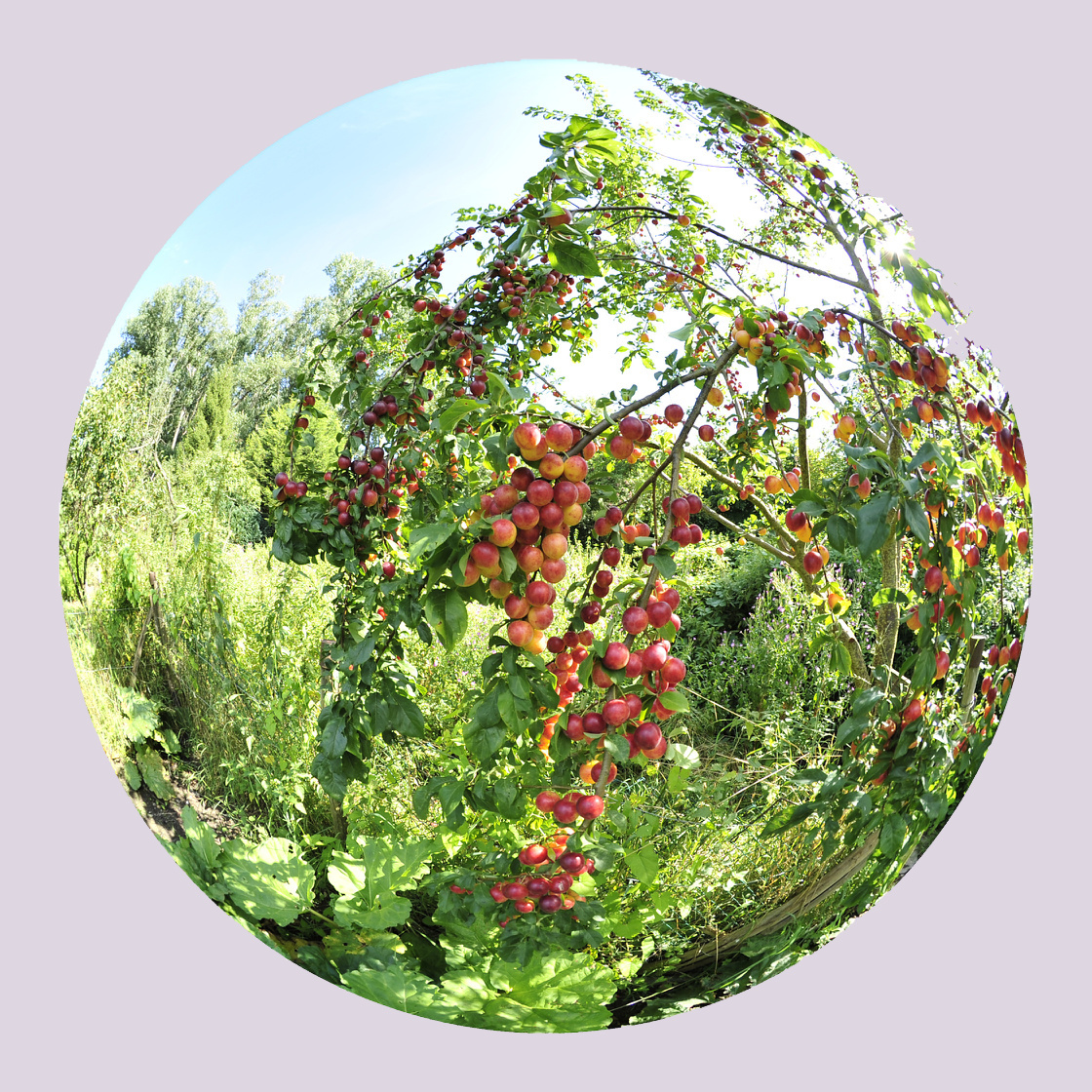
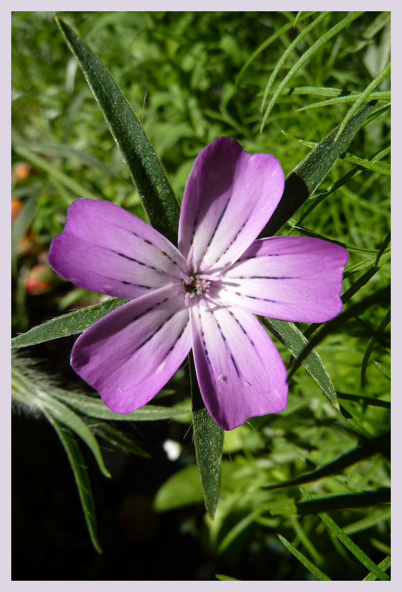
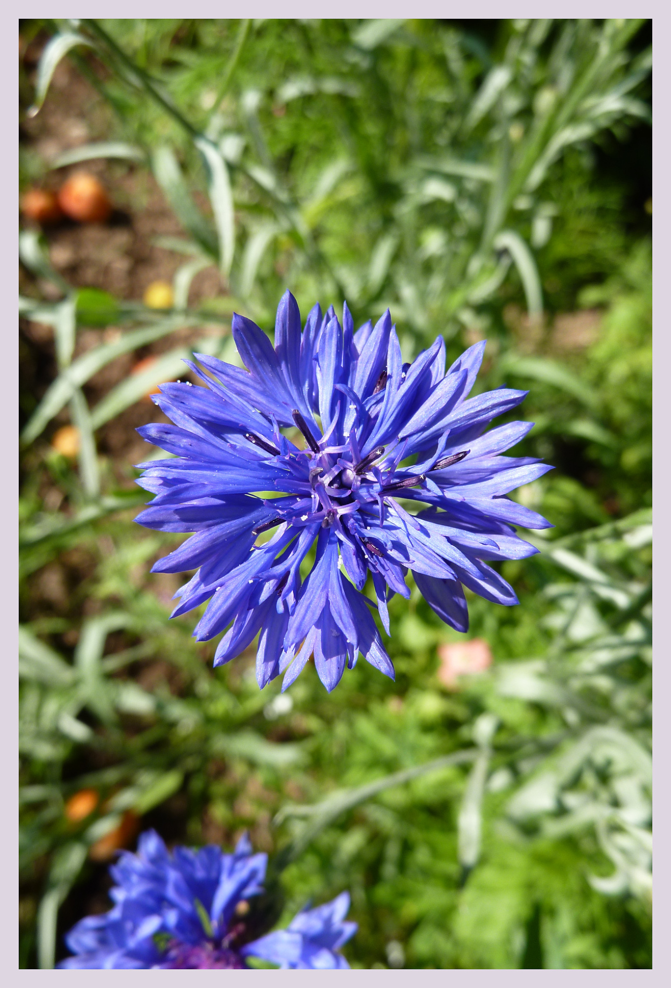
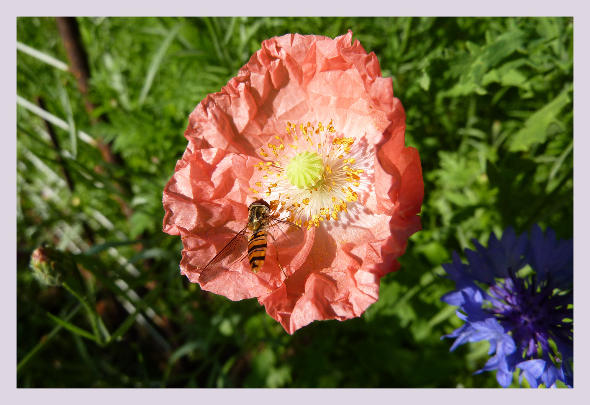
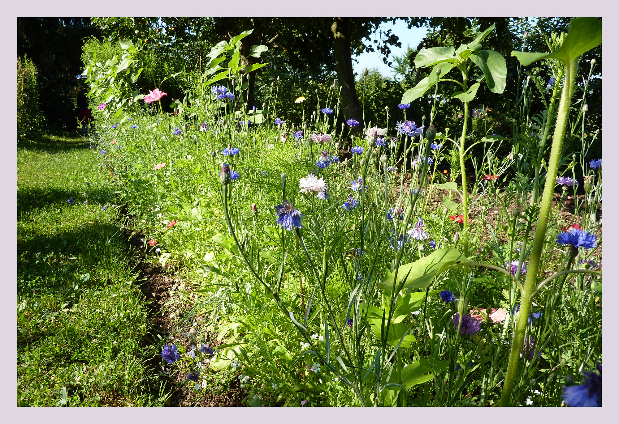
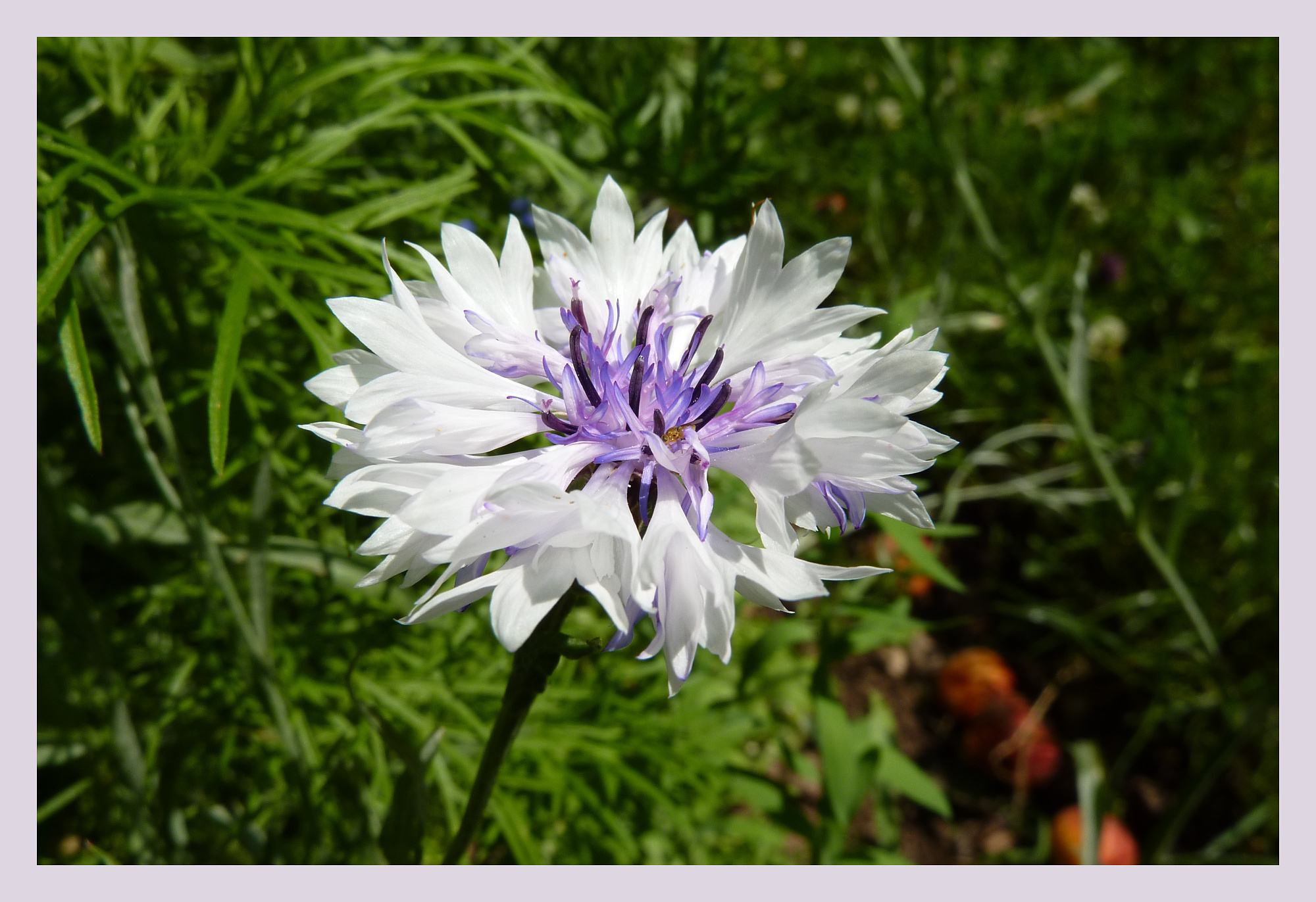
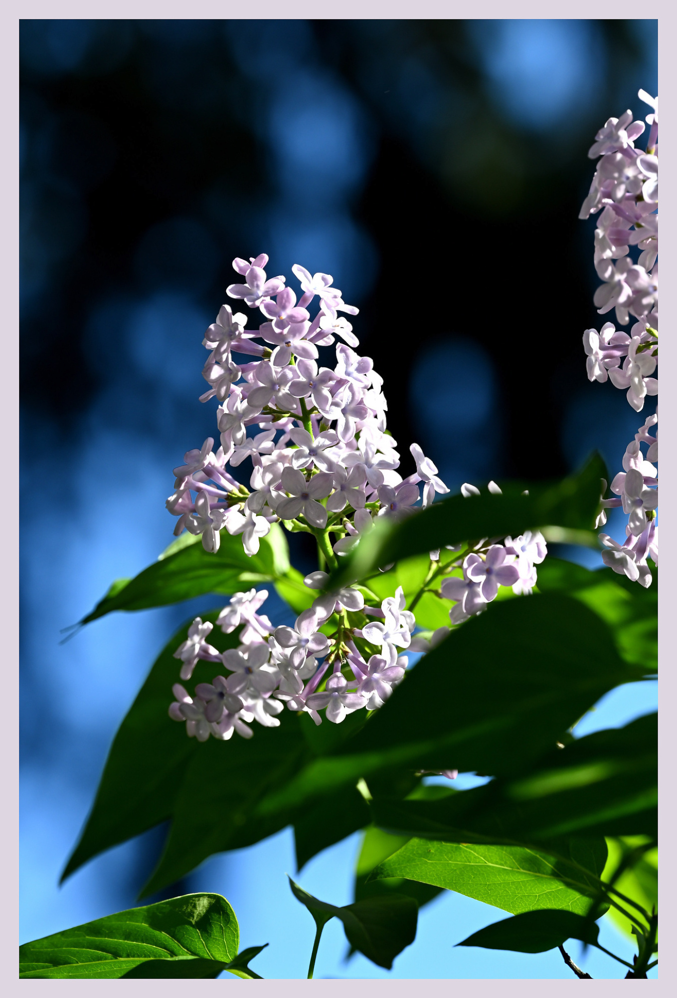
Frühlingsblumen 💐🪻
[ ] 🌧
[✓] 🌞1/320s f/6,3 ISO 100/21° 105mm f/2,8 VR
1/250s f/6,3 ISO 180 16-50mm f/3,5-6,3 VR f=50mm/75mm
1/1000s f/6,3 ISO 200/24° 24-70mm f/2,8 f=70mm
1/2000s f/4,5 ISO 200/24° 24-70mm f/2,8 f=44mm
1/2500s f/4,5 ISO 200/24° 24-70mm f/2,8 f=70mm
1/250s f/8 ISO 200/24° 8mm f/3,5
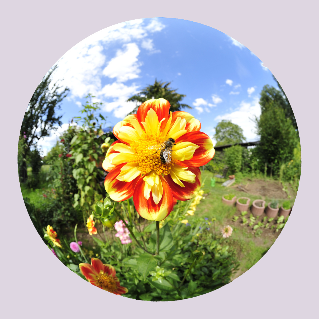
1/320s f/9 ISO 200/24° 8mm f/3,5
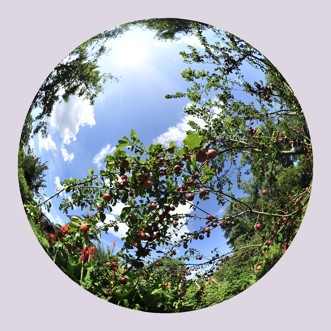
1/125s f/5,6 ISO 200/24° 8mm f/3,5
1/500s f/4,5 ISO 80/20° f=25mm
1/400s f/4 ISO 80/20° f=25mm
1/500s f/4,5 ISO 80/20° f=25mm
1/250s f/4 ISO 80/20° f=25mm
1/500s f/5,6 ISO 80/20° f=25mm
1/250s f/5,6 ISO 110 105mm f/2,8 VR
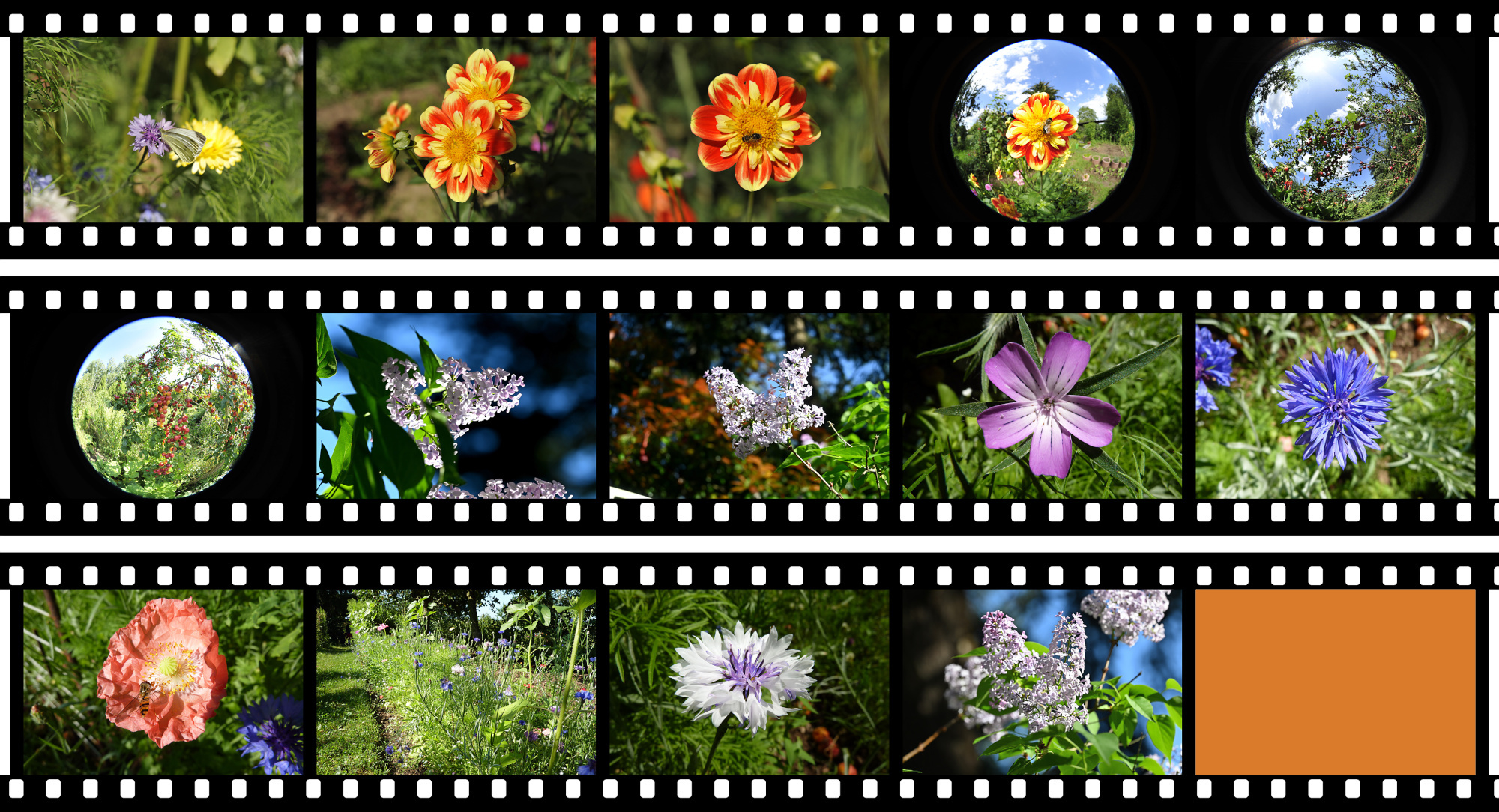
orange mask #D97B2B, RGB(217,123,43) -
Selling Lenses 🛒
Selling lenses (and 📷) is easy. At least according to the offers from small and large camera dealers. Advertising with 'up to 70% of retail' should have the focus on 'up to'.
Here is my result: Quotes from camera sites and then selling at eBay at the average eBay price.
If the value is 0, they did not want the lens.Lens B&H Glazer's Kenmore MBP eBay 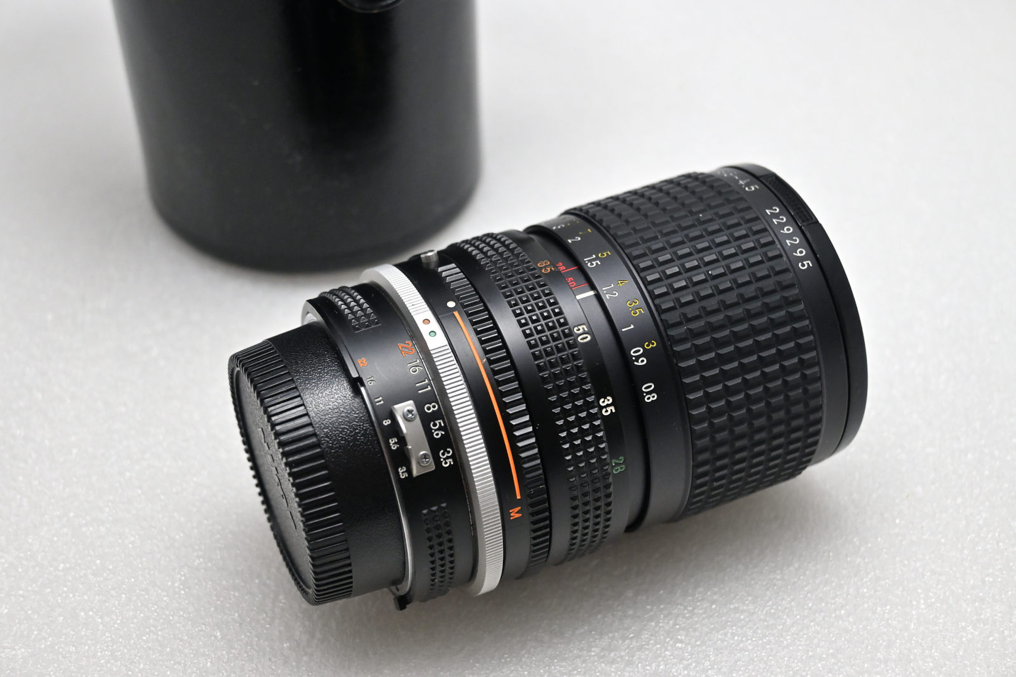
Nikon AI-S 28-85 f/3.5-4.5 125 35 30 0 95 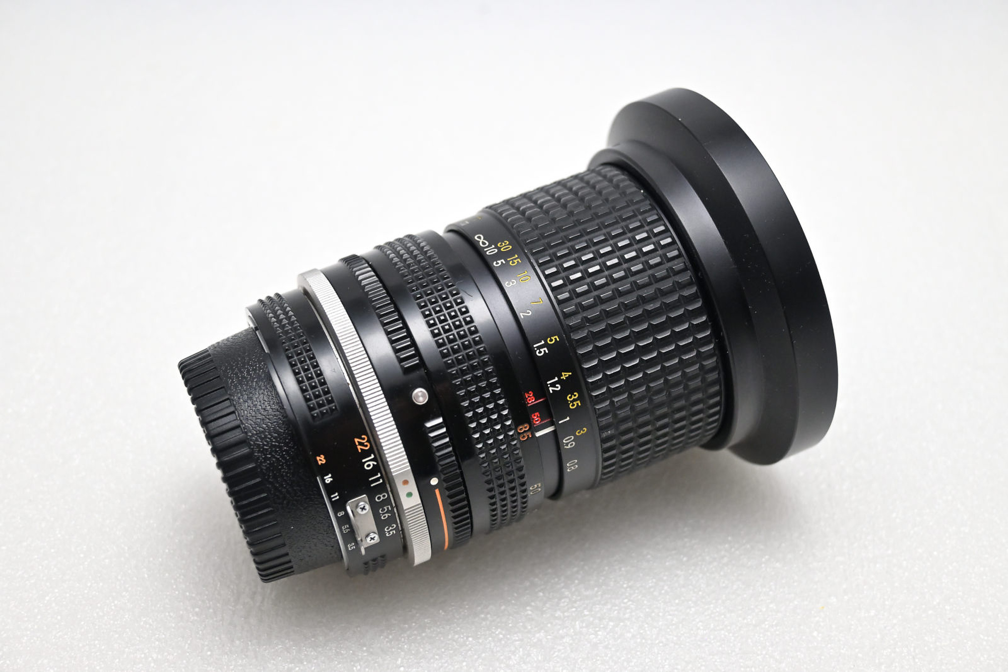
Nikon AI-S 28-85 f/3.5-4.5 125 35 30 0 95 
Nikon 35-105mm f/3.5-4.5 AI-S 25 15 15 28 145 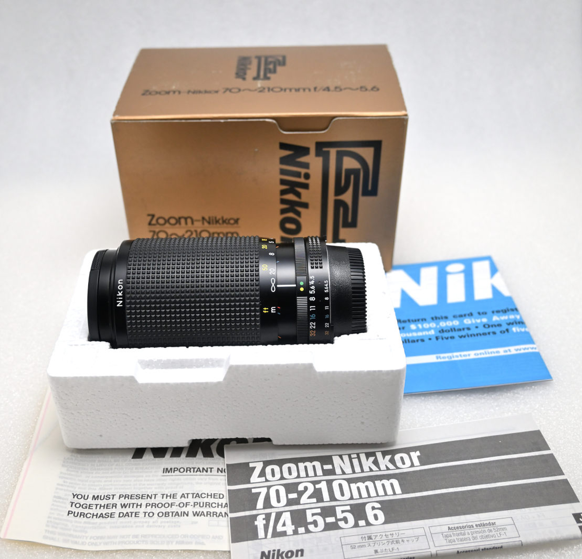
Nikon AI-S 70-210mm f/4.5-5.6 30 15 10 0 95 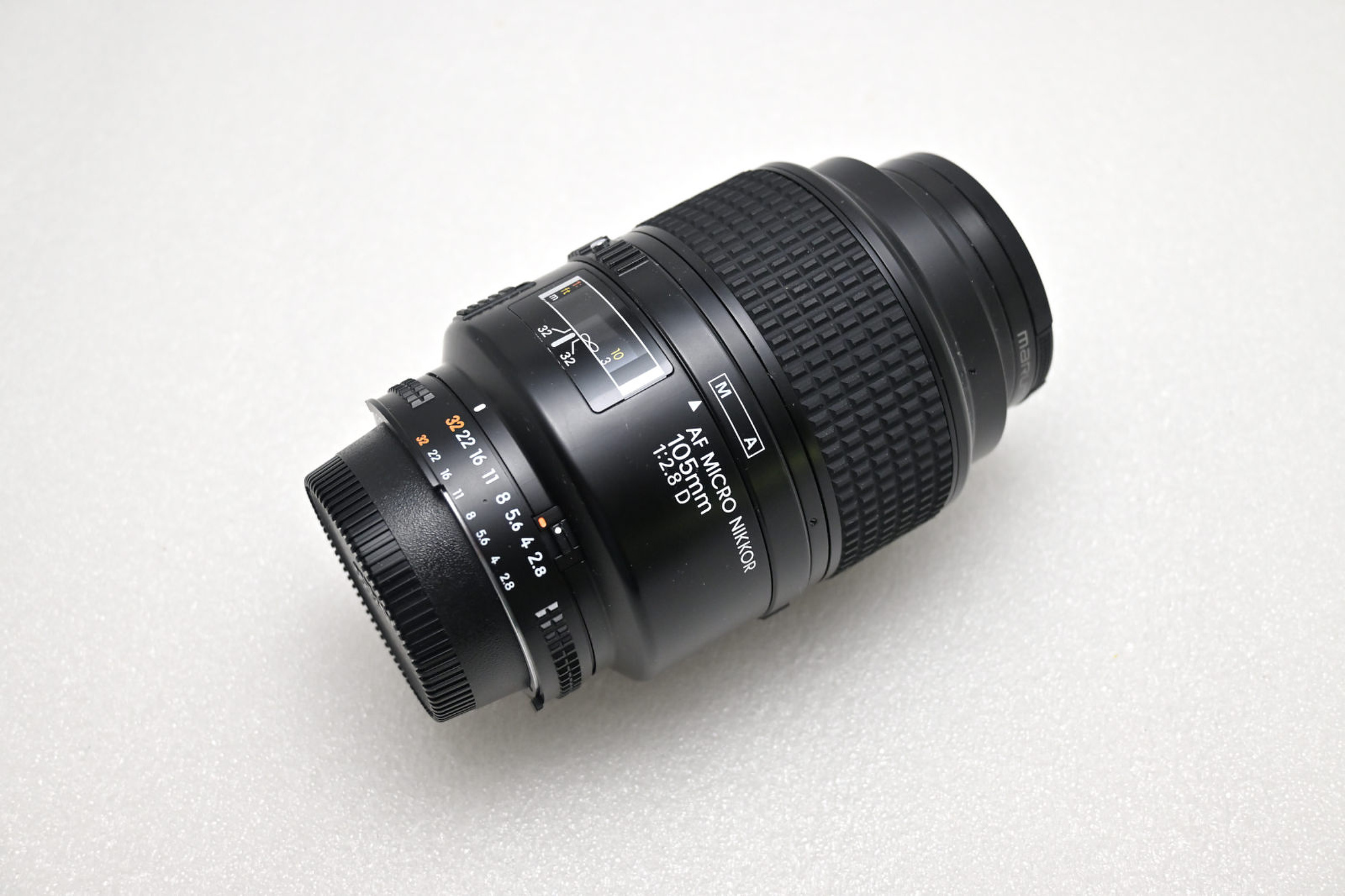
Nikon AF 105mm f/2.8 D Macro 75 72 100 118 185 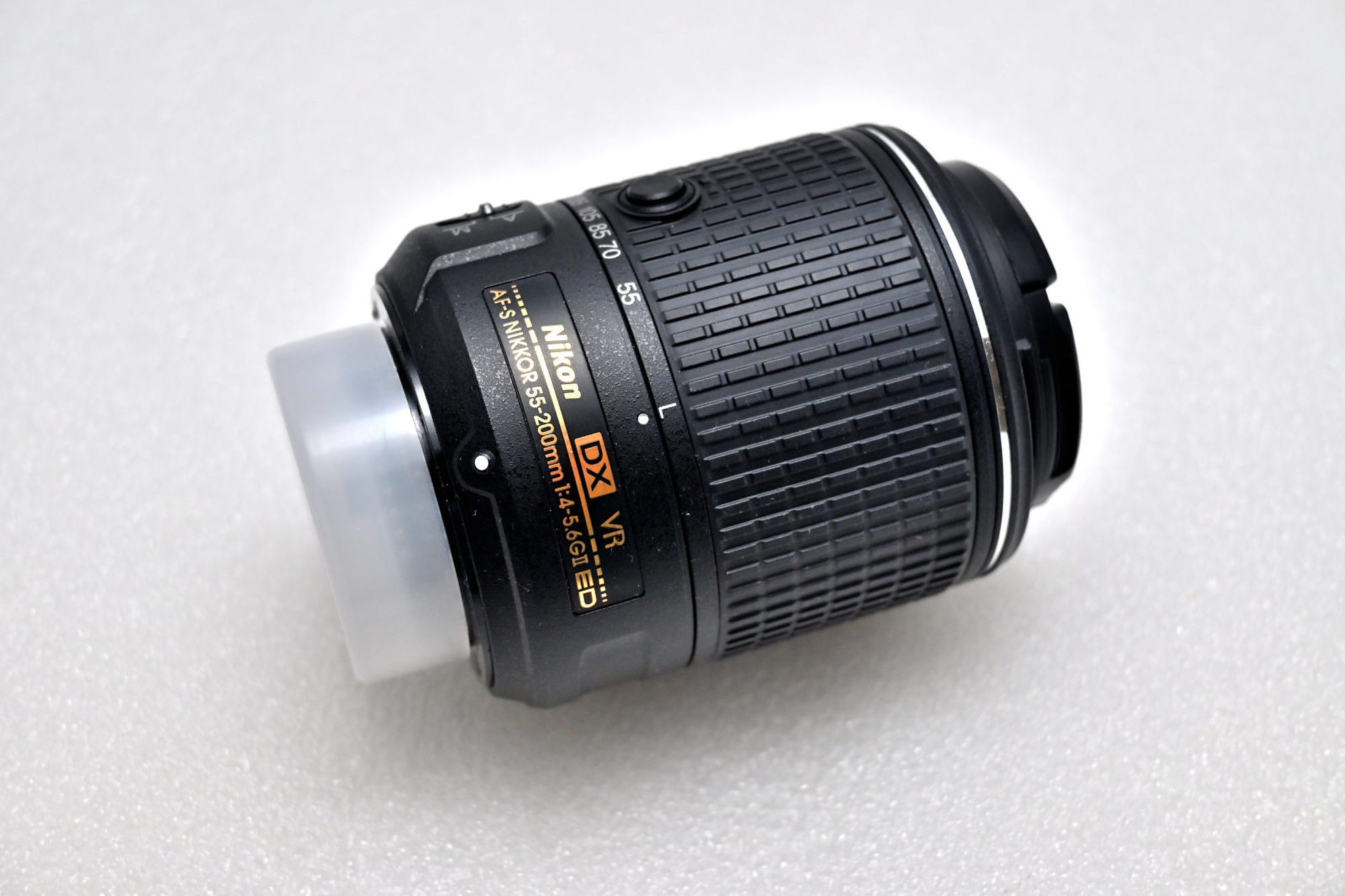
Nikon 55-200mm f/4-5.6G ED VR II AF-S D 50 27 10 42 115 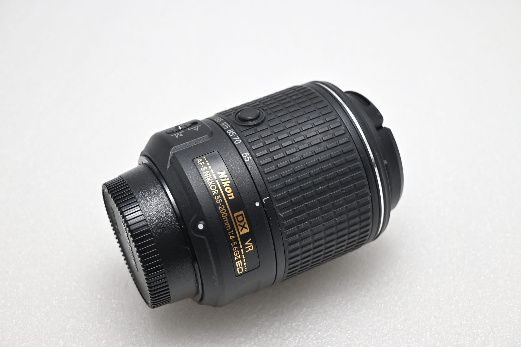
Nikon 55-200mm f/4-5.6G ED VR II AF-S D 50 27 10 42 115 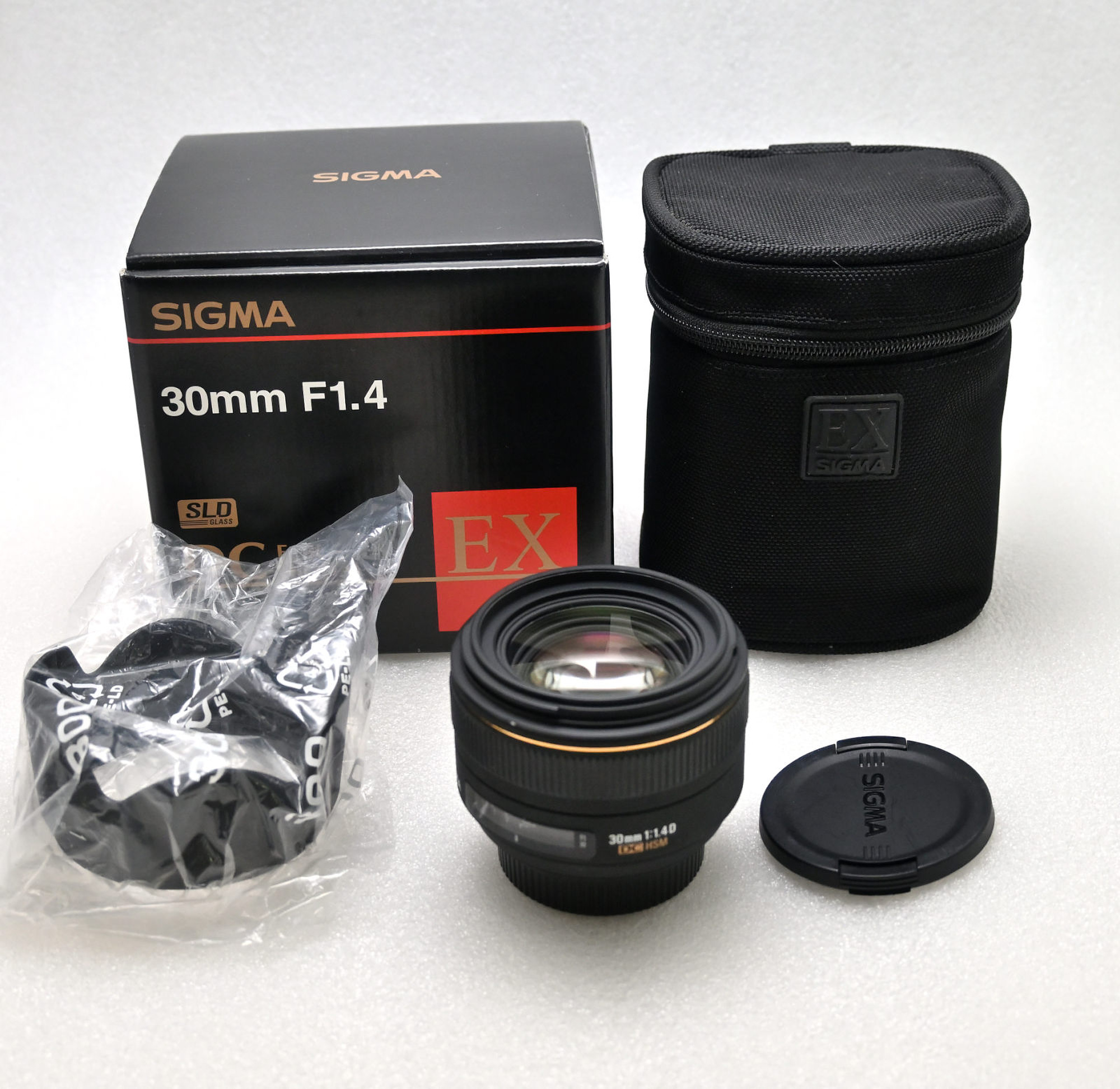
Sigma 30mm f/1.4 DC HSM 70 52 50 72 185 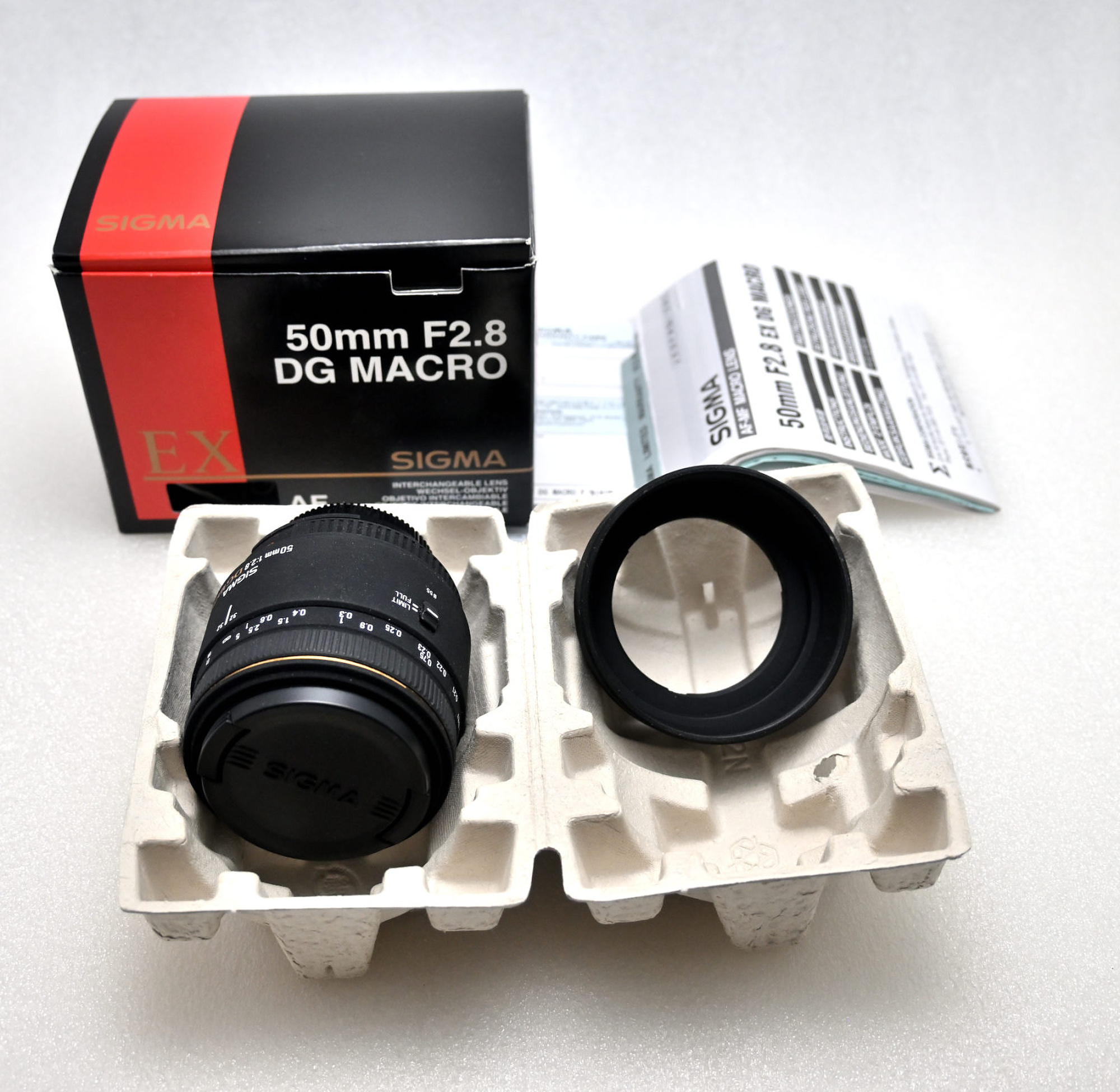
Sigma 50mm f/2.8 DG Macro 75 0 30 128 165 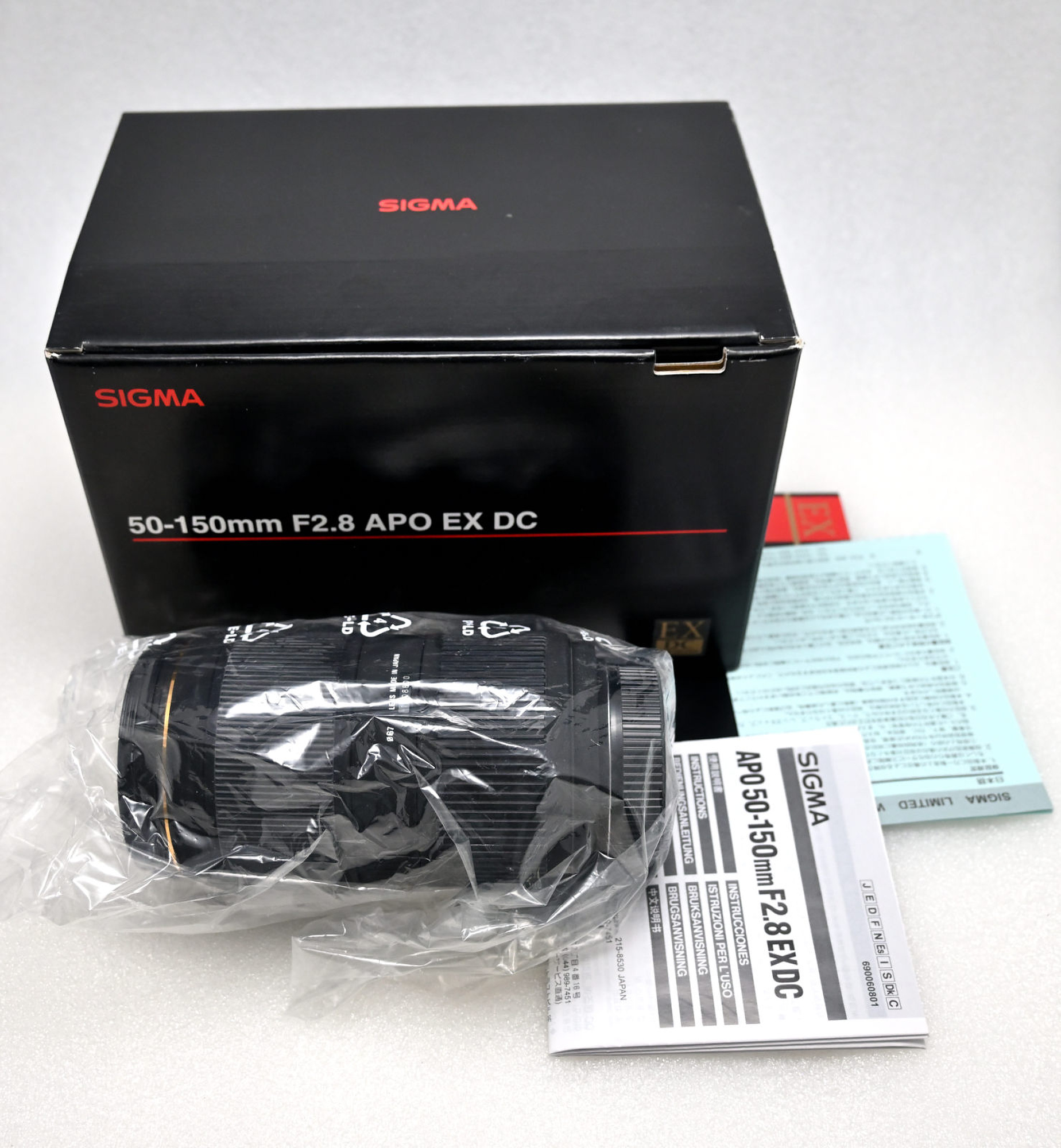
Sigma 50-150mm f/2.8 EX DC APO HSM 0 125 115 121 385 
Tokina 500mm f/8.0 Mirror Lens for Nikon 0 0 35 125 165 Ʃ 625 403 435 676 1745 Sigma 8mm f/3.5 EX DG Fisheye 140 50 125 87 Nikon AF 50mm f1.4D 75 42 65 55 The quote from Adorama required to send in the lenses, but I was told the estimate would be around 500.
B&H's is similiar price, but there is an exception for the Nikon AI-S 28-85 f/3.5-4.5. Seems like a very sought-after lens, but not for MBP.
So far, B&H pays best for those (vintage) lenses.The last two lenses I decided to keep, but I had them added to the quote to check. Would you sell for this price?
Update:
Lenses have been sold on eBay, with an approximate 20-25% fee deducted. The only exceptions are the two Nikon AI-S 28-85mm f/3.5-4.5, which I traded to B&H for a tax-free voucher. They are still listed for sale there1, quietly gathering digital dust.
The lens shelf now looks more intentional and less like a clearance bin.
-
Both lenses were in like-new condition and nearly indistinguishable from each other, yet they are listed with noticeably different condition ratings and prices. So much for consistency in evaluations. ↩
-
-
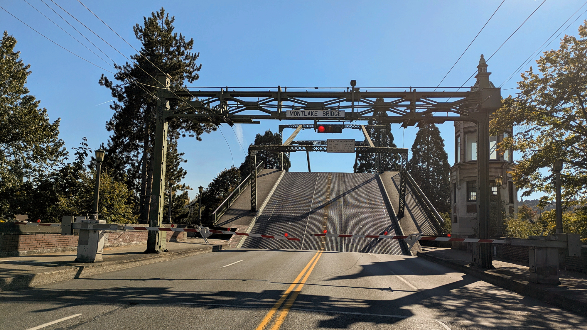
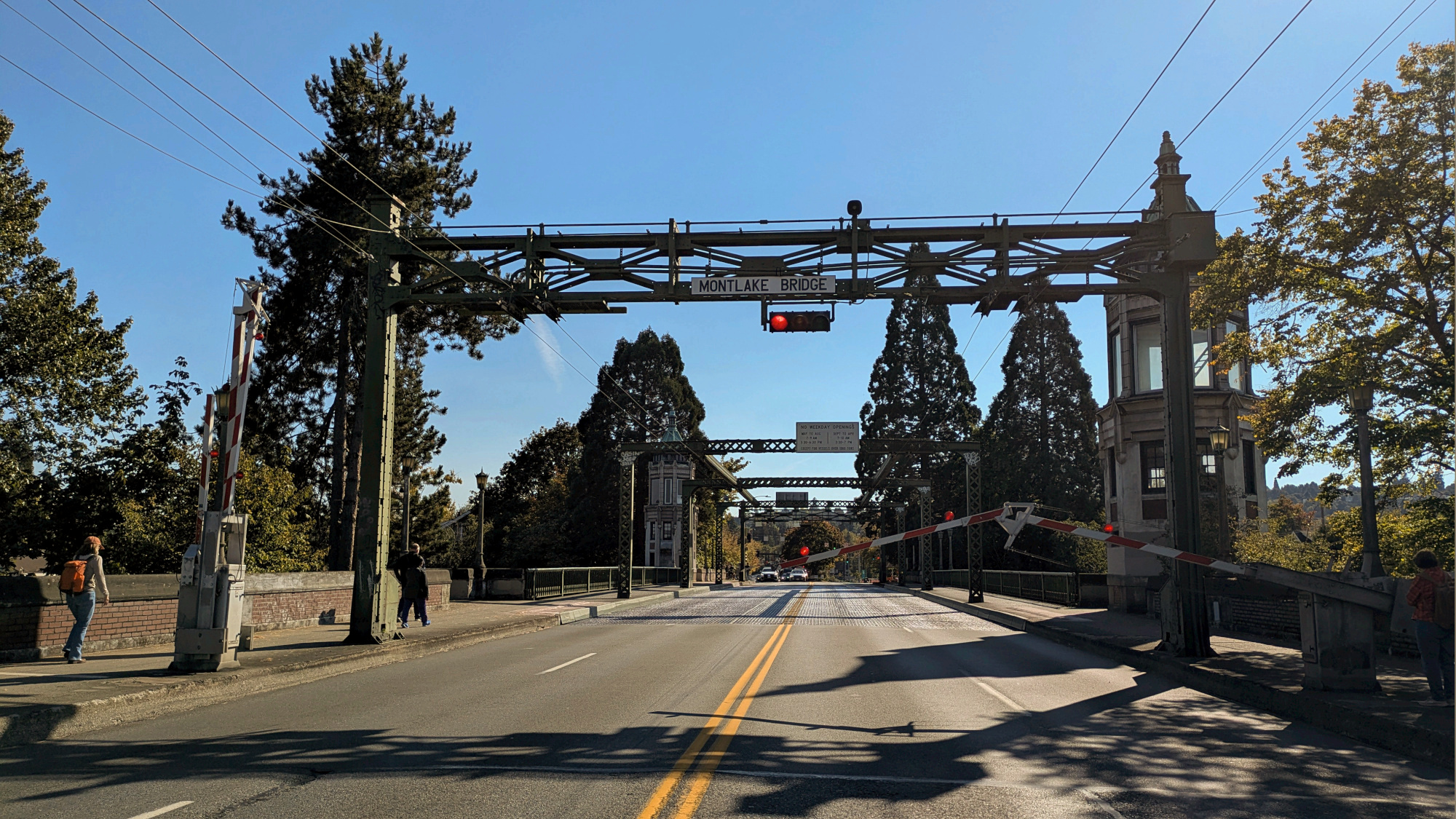
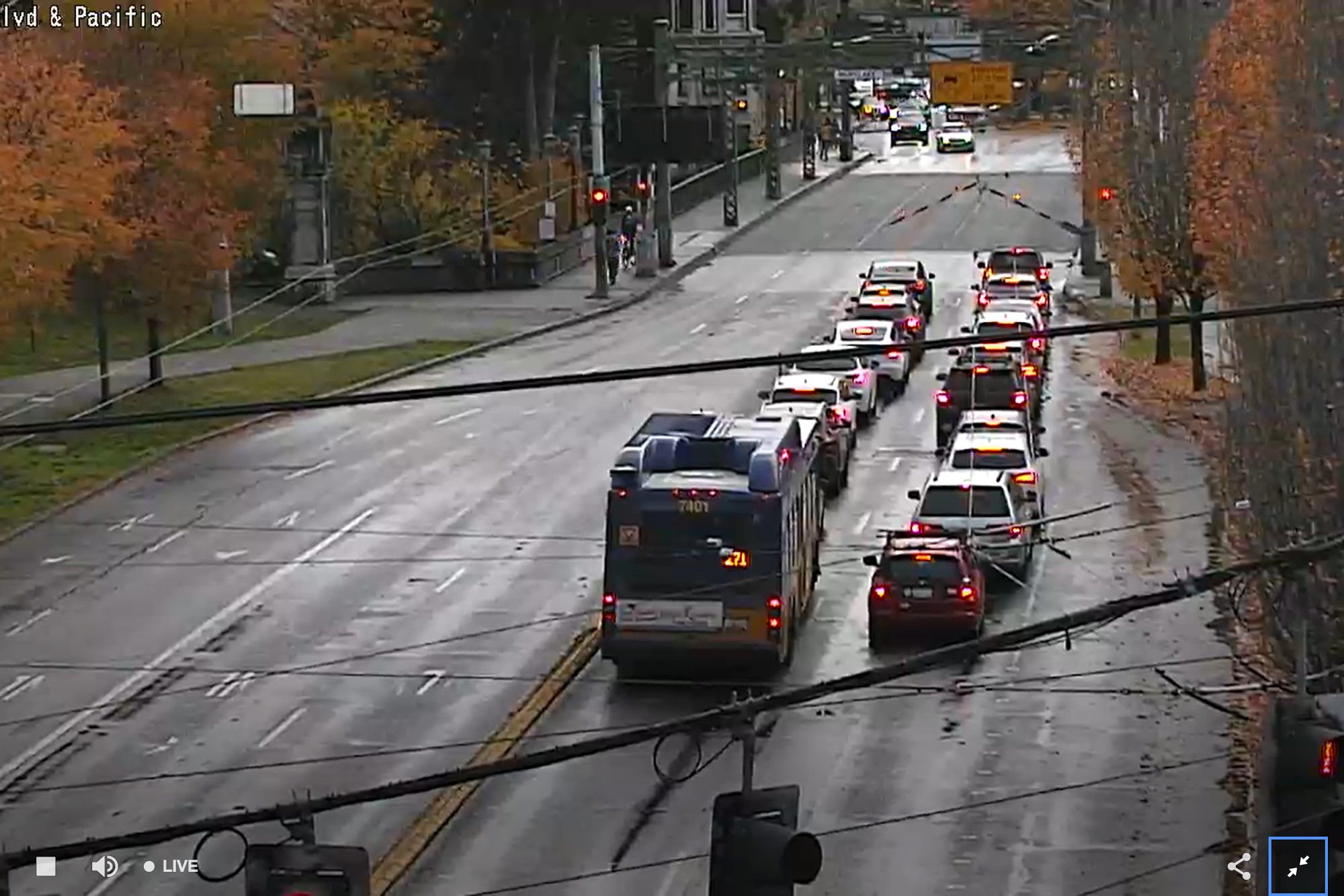
Montlake Bridge
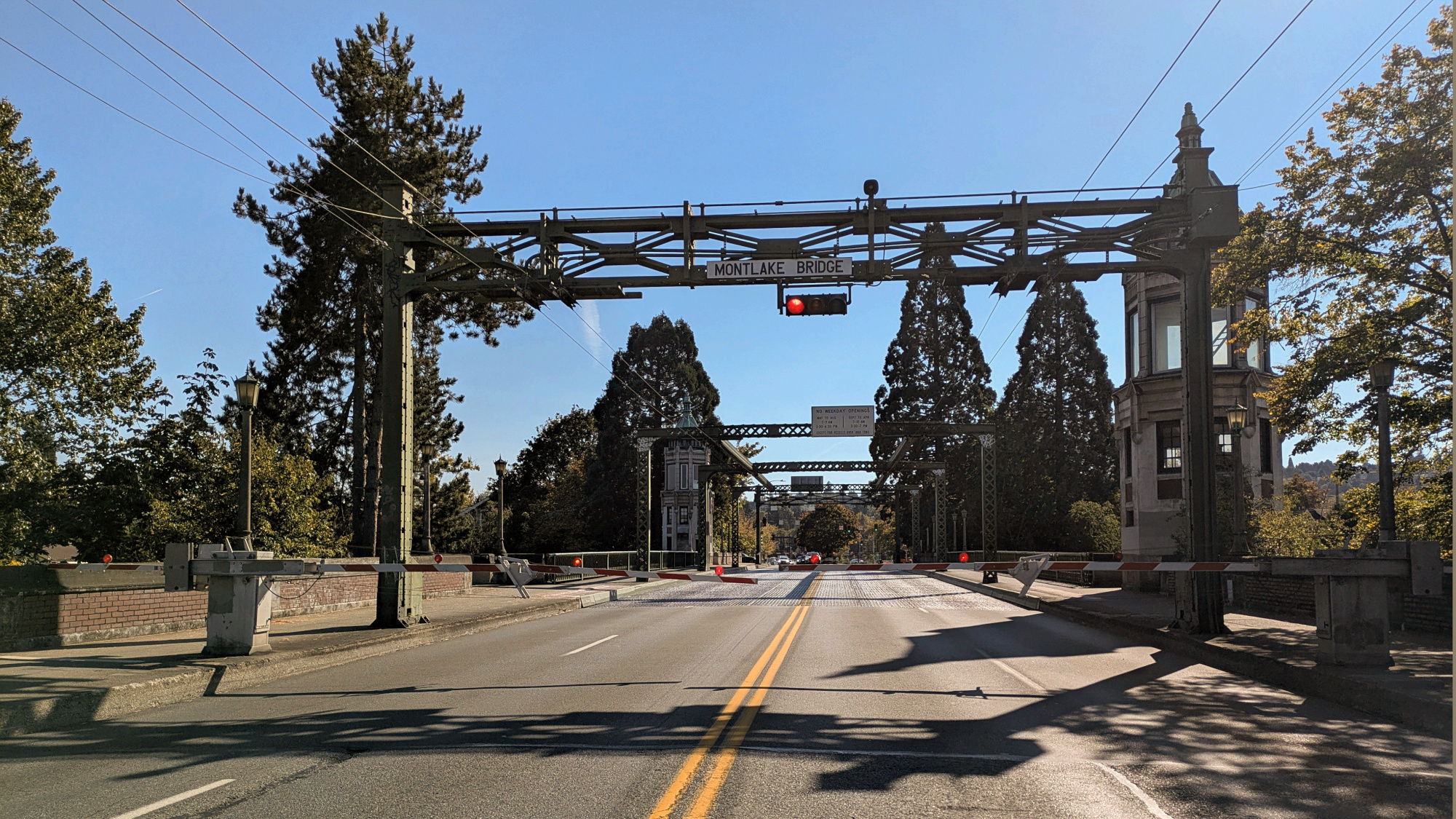
I often pass the Montlake Bridge on my way to UW, but today was different: the bridge opened for water traffic just as I got there. The light turned red, and the bars descended, signaling the bridge's closure. I watched as the bridge slowly lifted to allow a sailboat to pass through, but I only saw the sailboat's mast passing by. Remarkable to see the massive structure rise and then descend back into place.
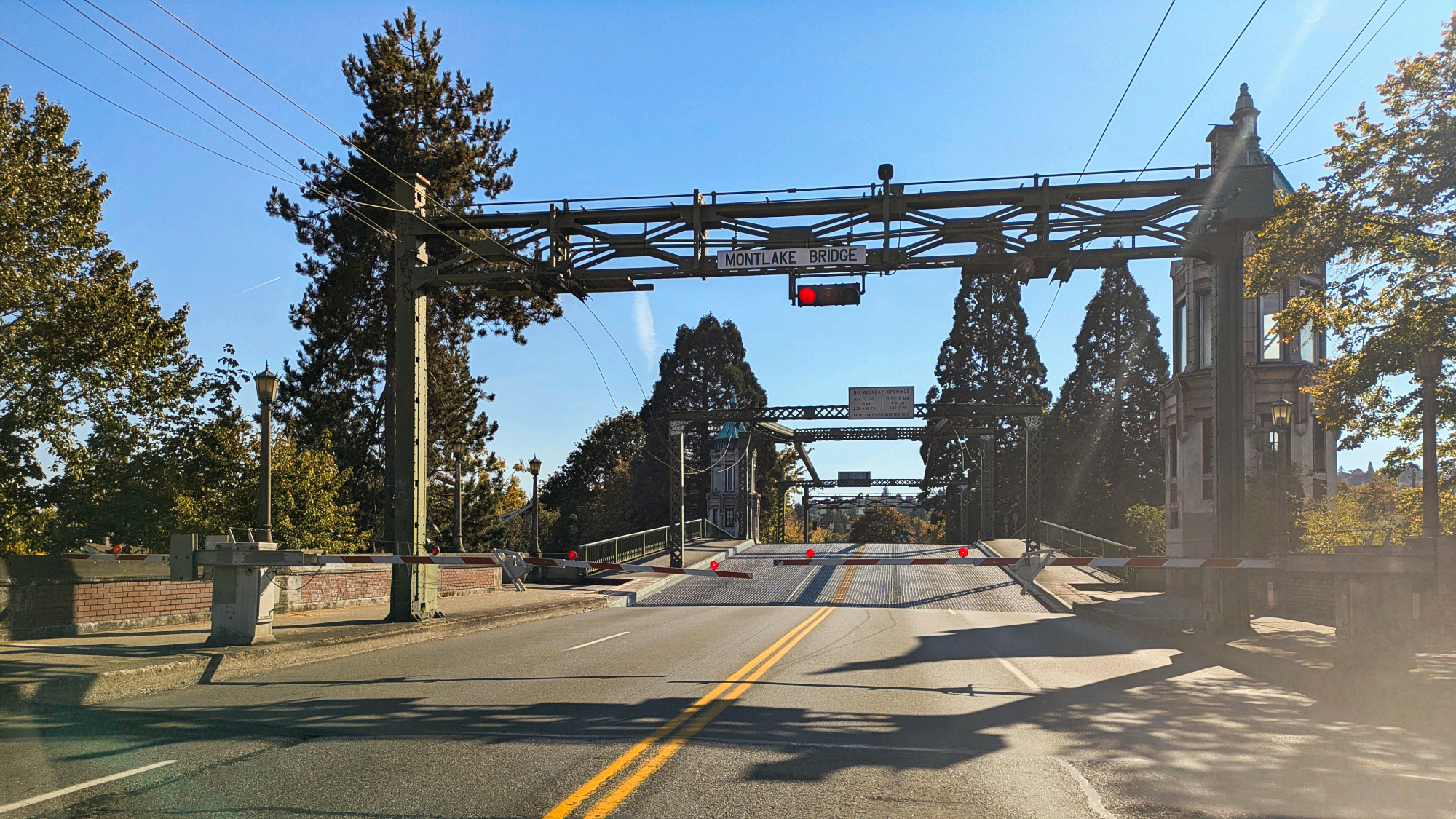
14:00:56, Bridge starting to open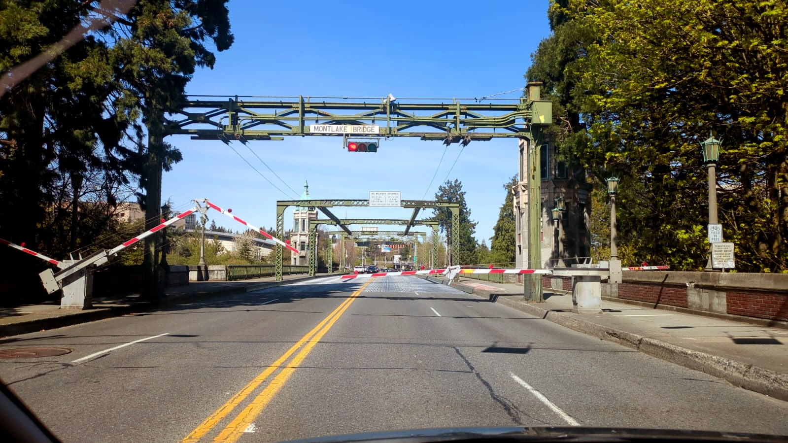
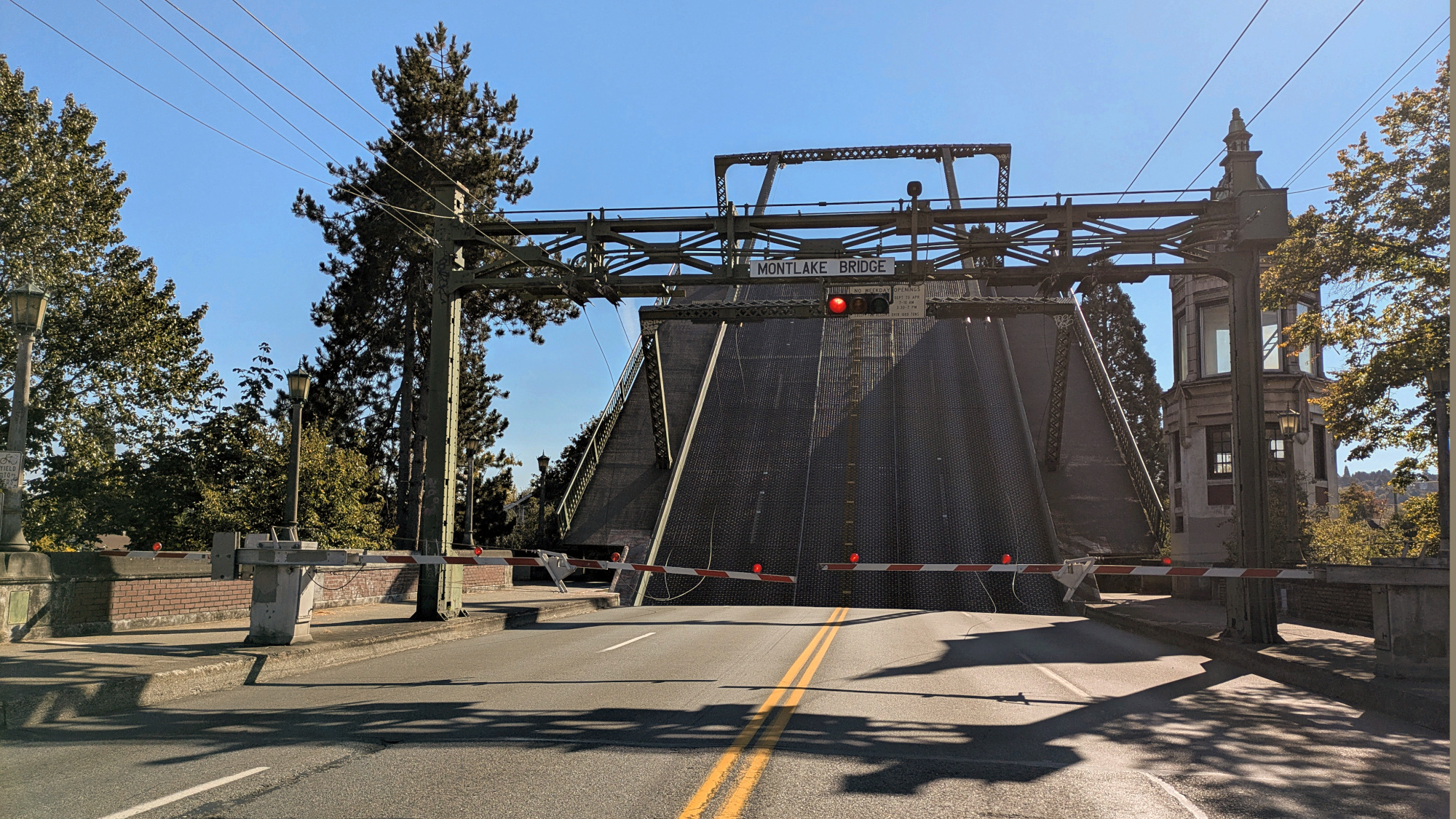
14:01:36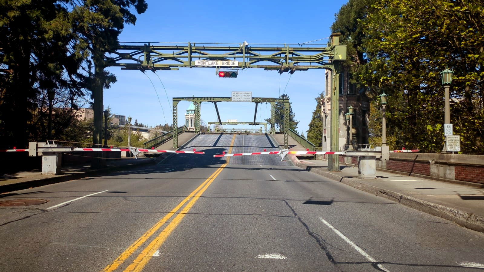
14:01:52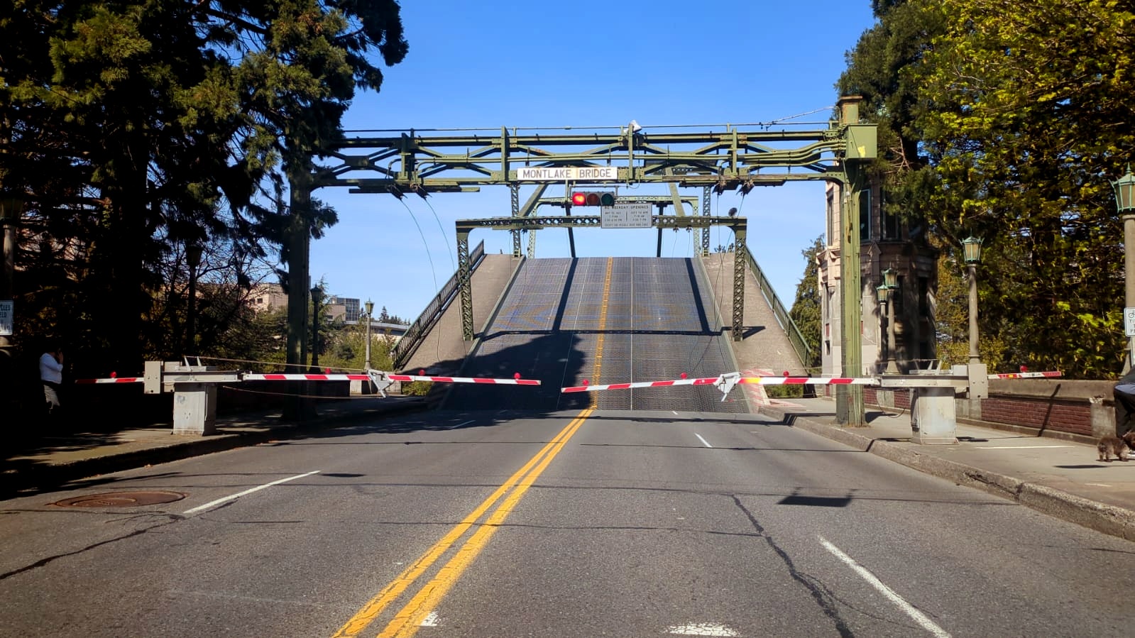
14:02:06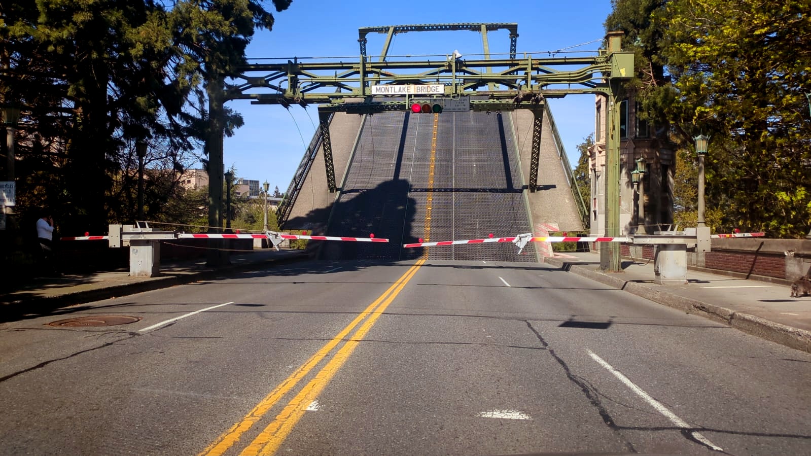
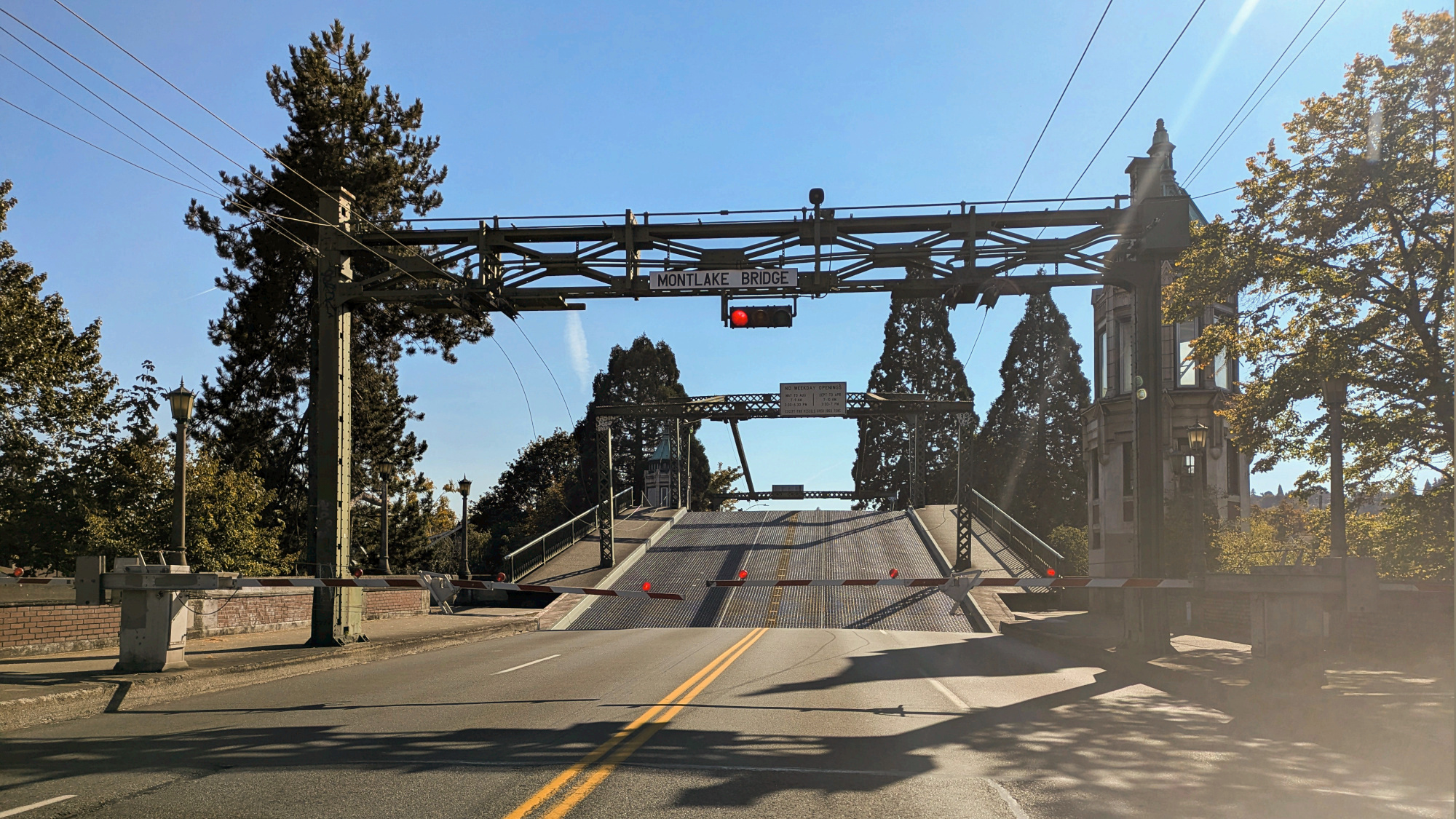
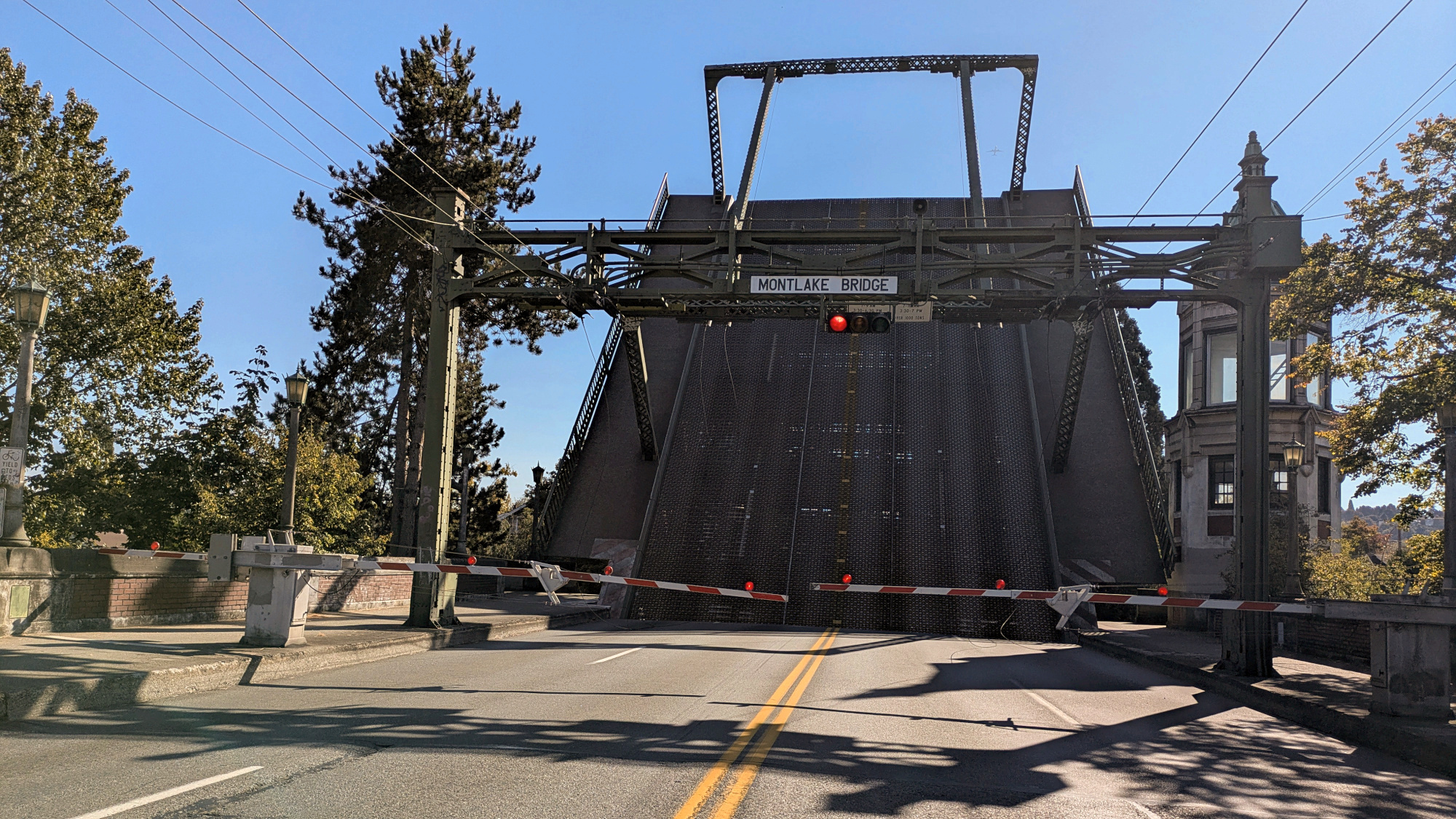
14:02:36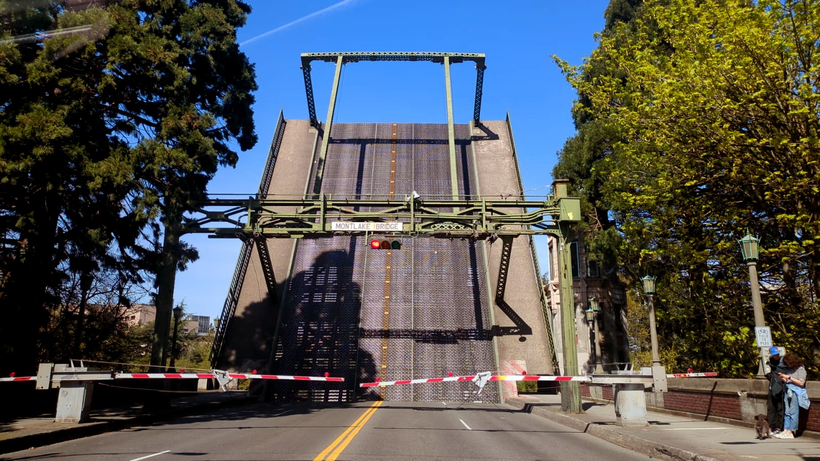
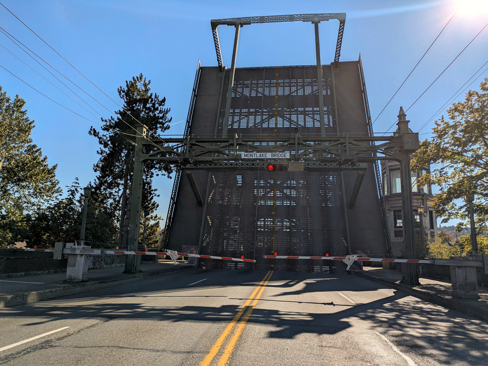
14:03:06, Bridge fully opened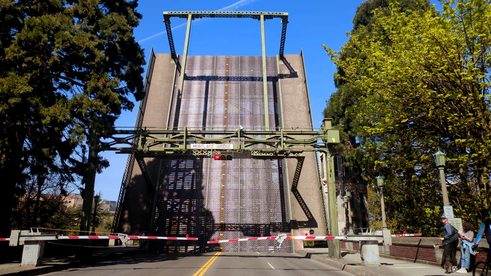
14:04:52, Bridge closing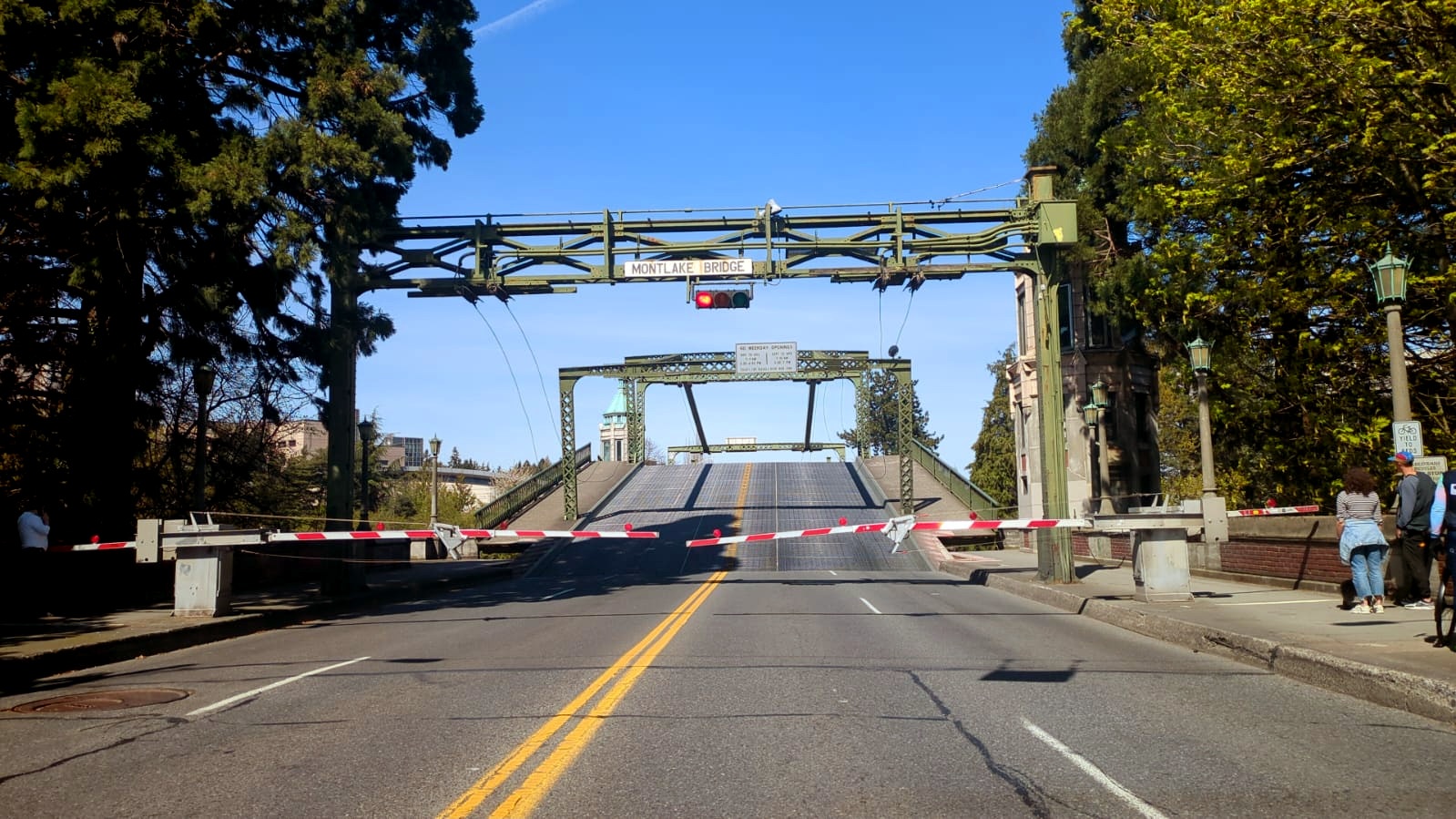
14:05:08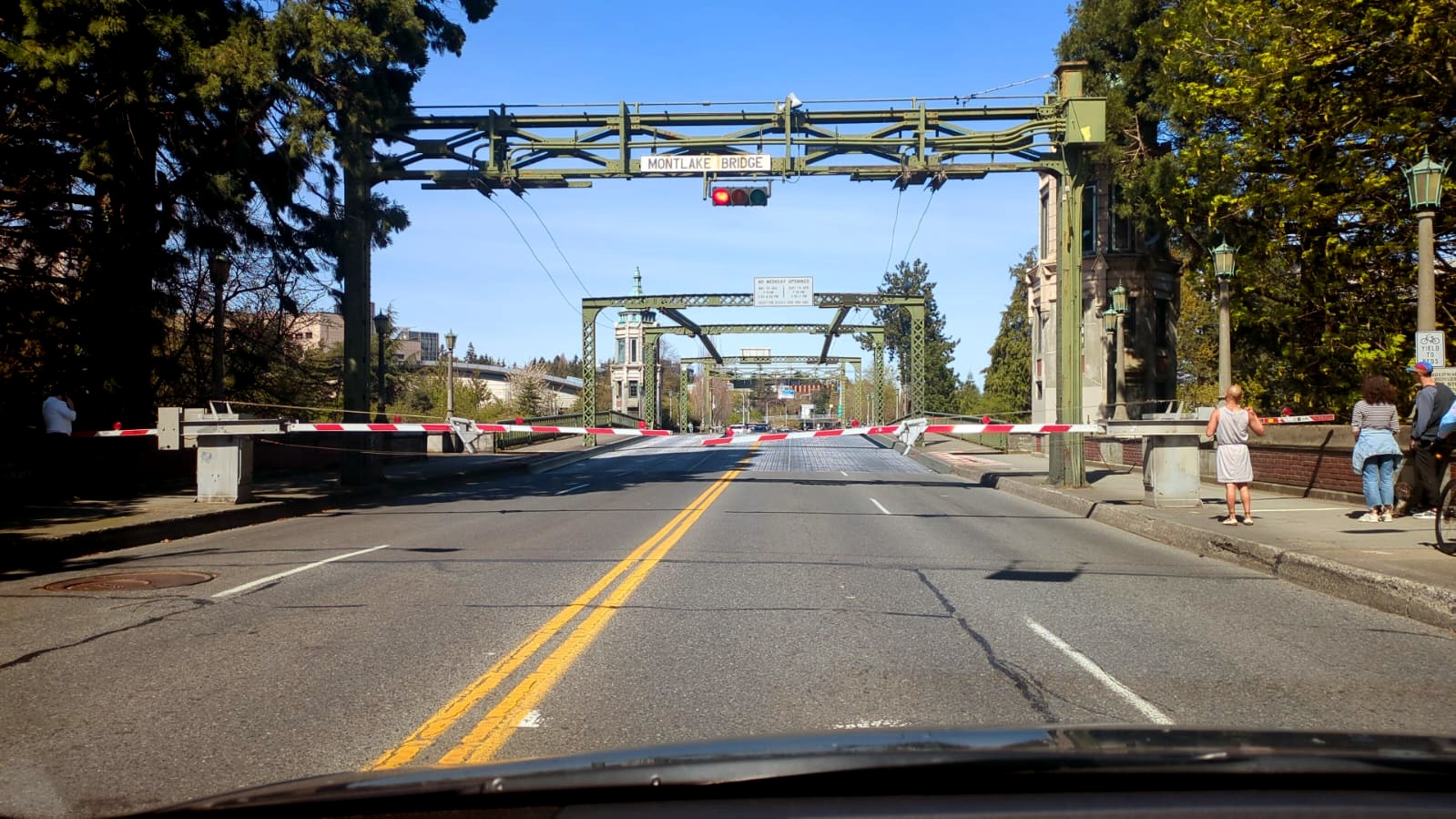
14:05:50, Bridge completed its cycle and traffic resumes in a few seconds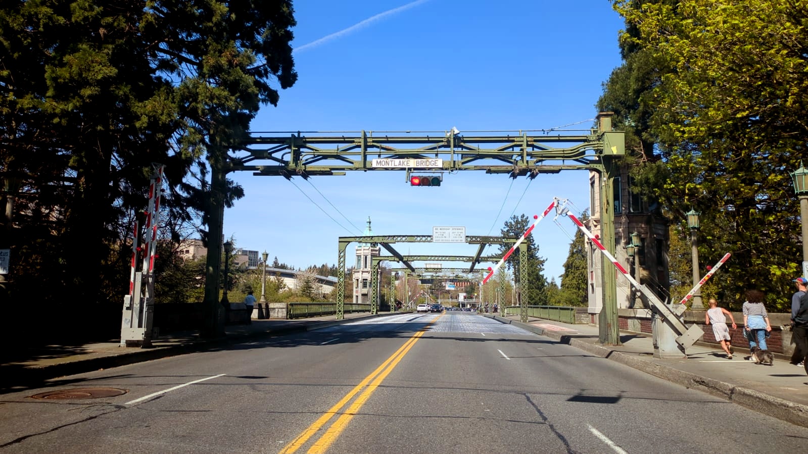
A few days later, I was on the other side of the canal while traffic stood still, watching the bridge rise and settle once more.

A few months later, I was first in line on that same route with a perfect view as the bridge began its cycle. The timing could not have been better. The red lights flashed, the gates descended, and the massive structure started its graceful ascent. Positioned at the very front, I could see every detail: the roadway lifting, the two halves opening, and the quiet pause at full height before the bridge eased back into place.
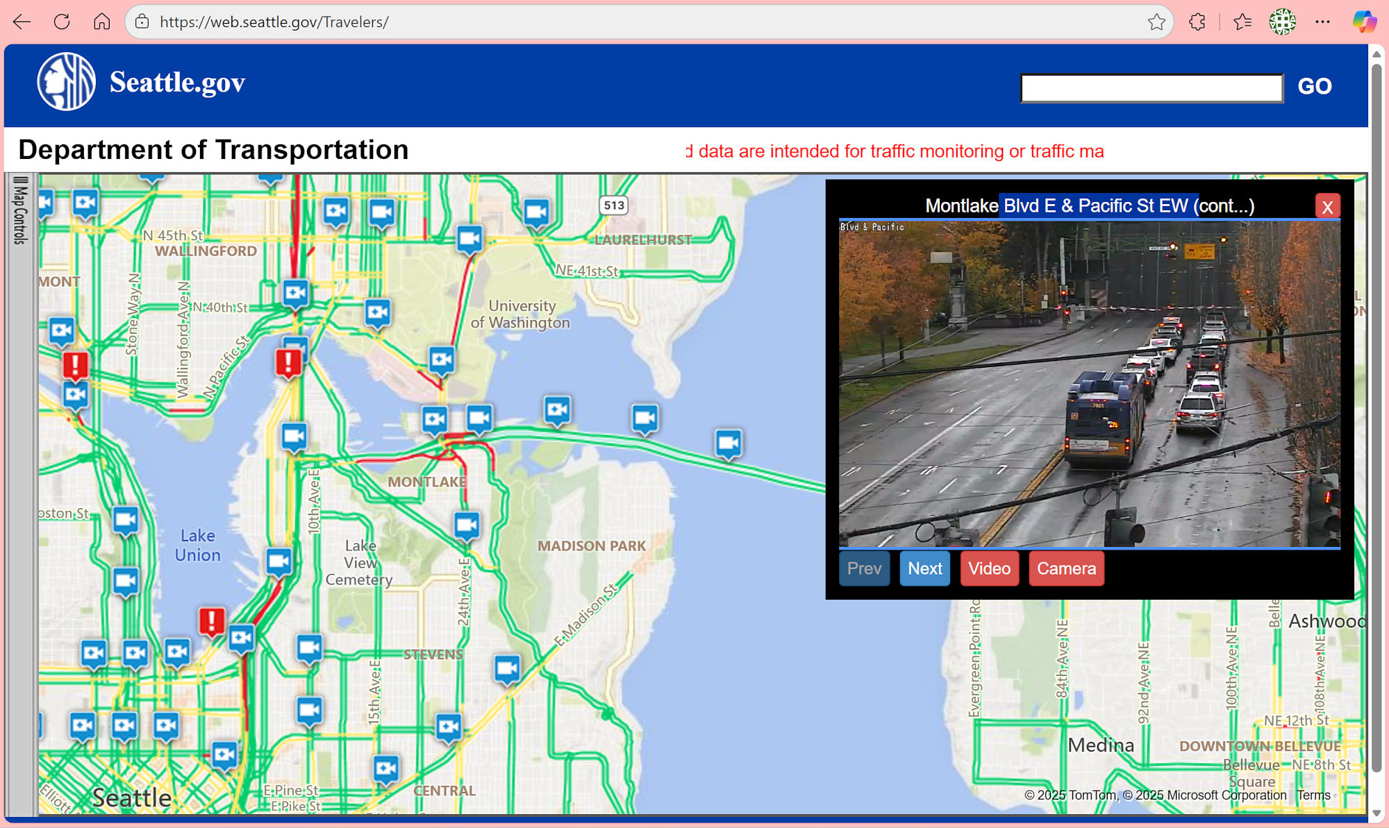
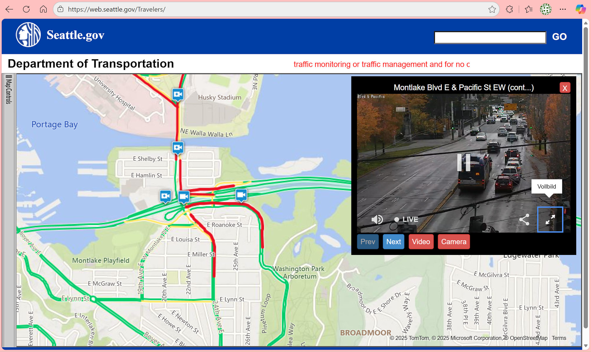
A while later, I checked the traffic and noticed the red lines of waiting cars on the map. Sure enough, the bridge was operating. Here are some screenshots from a different perspective:

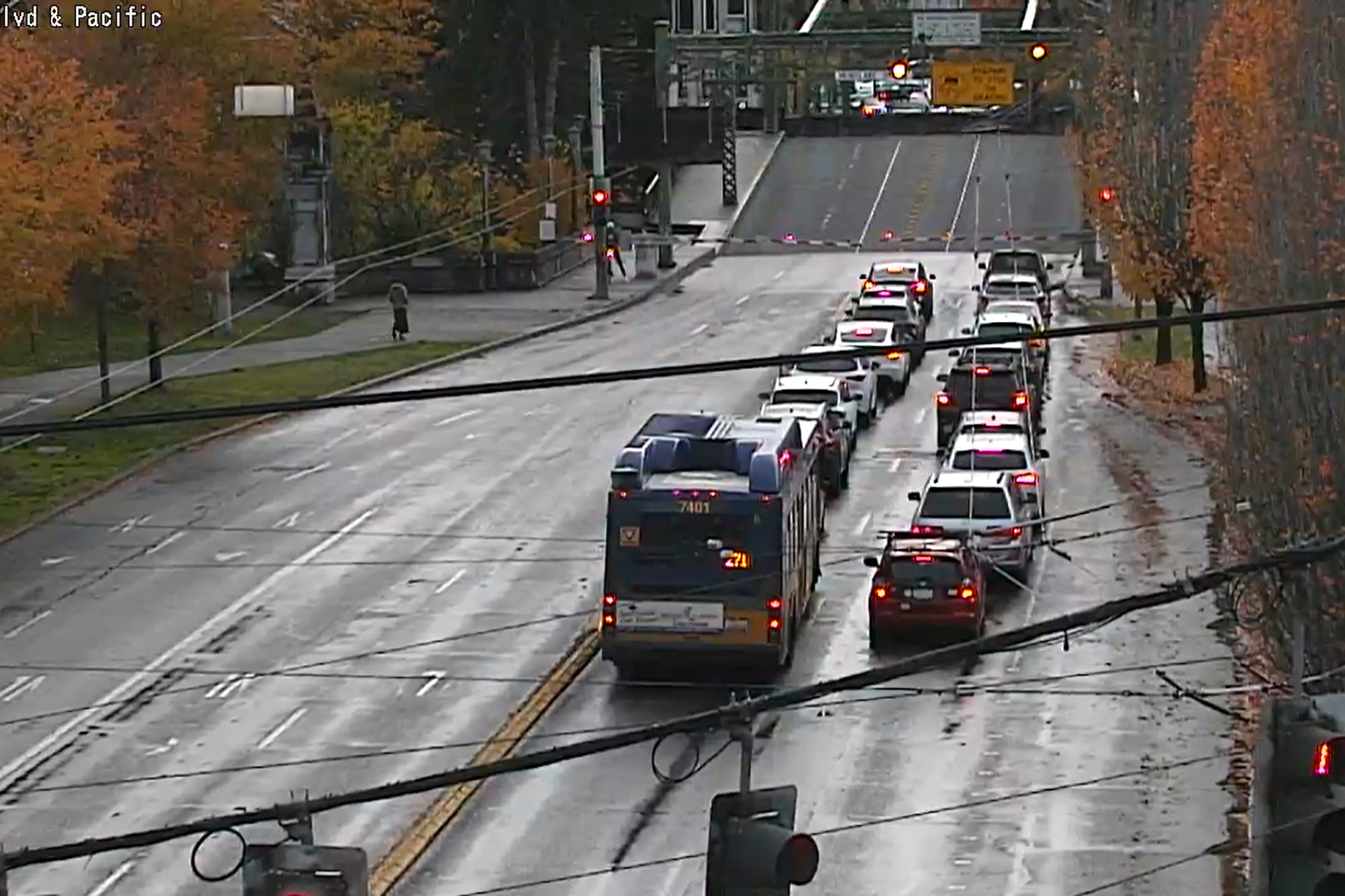
Gates open
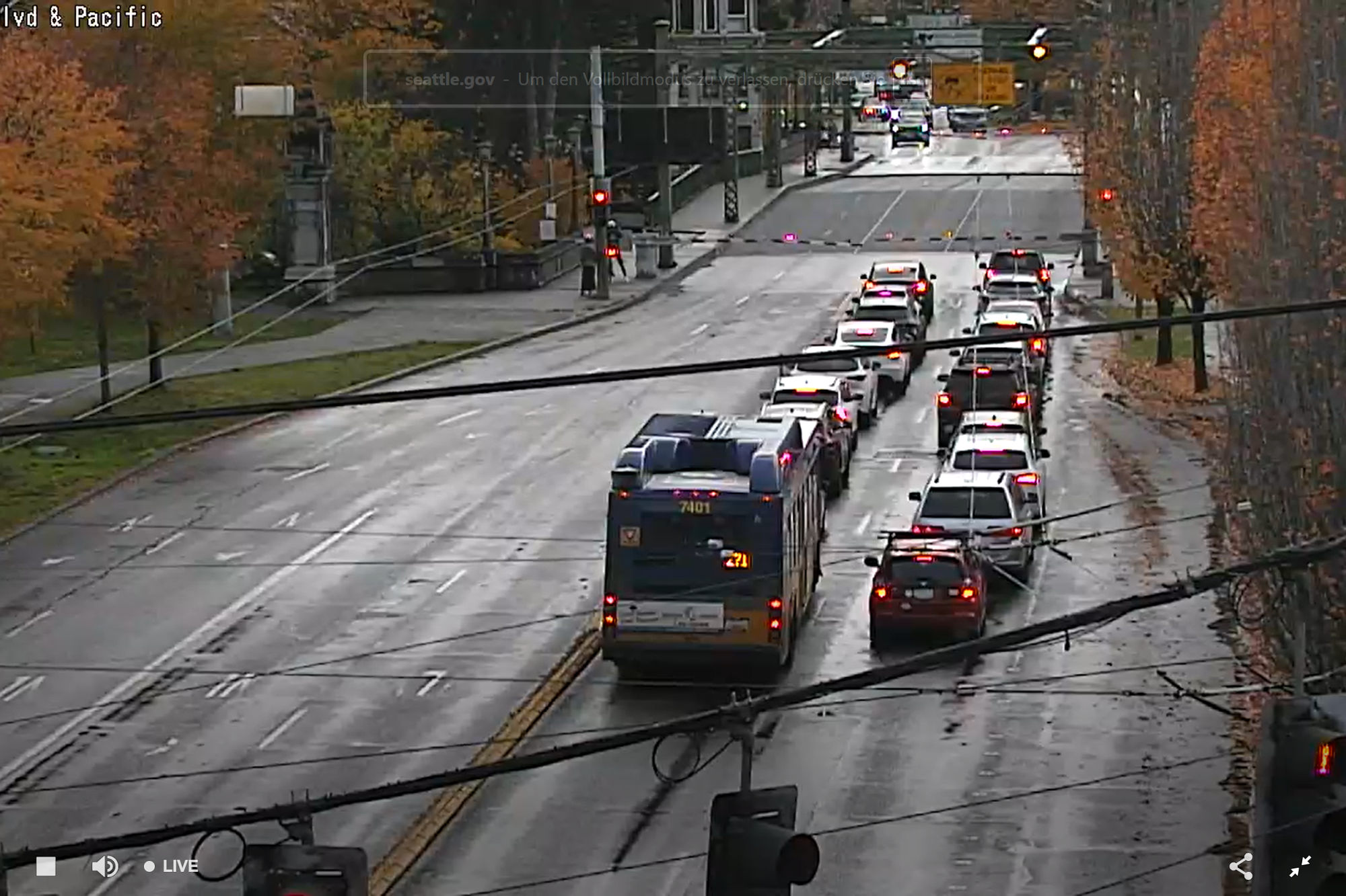
Traffic resumes
See also Lake Washington Bridges.
-
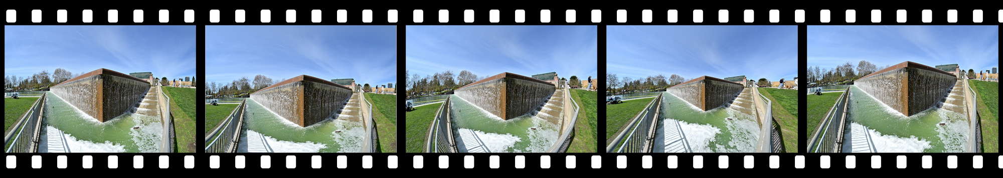
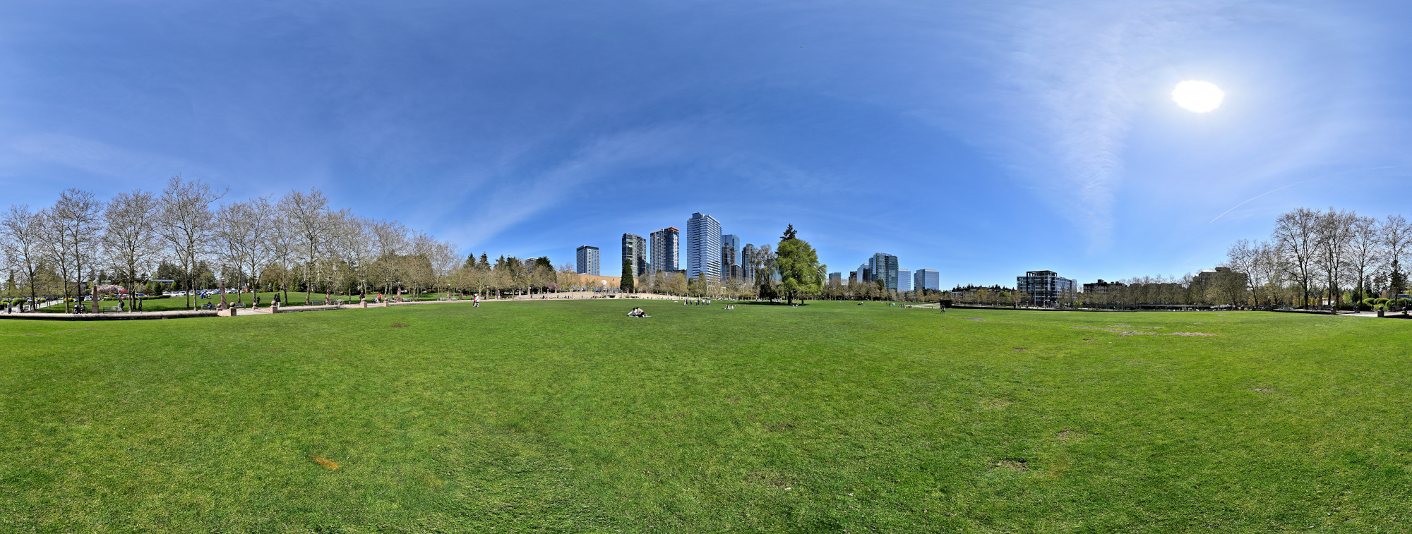
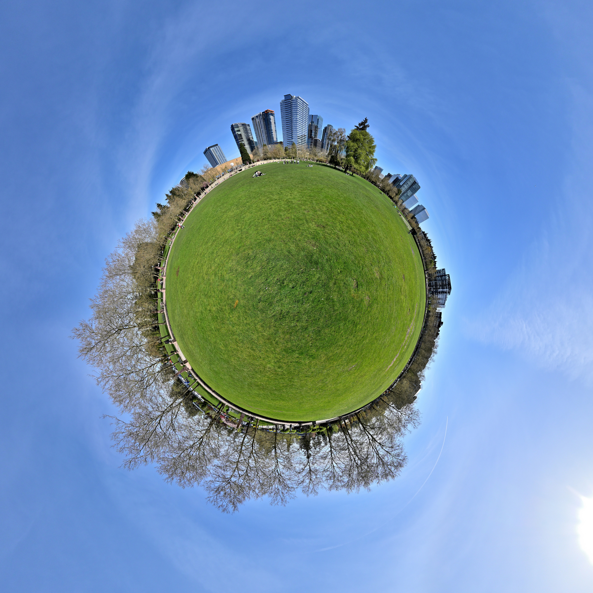
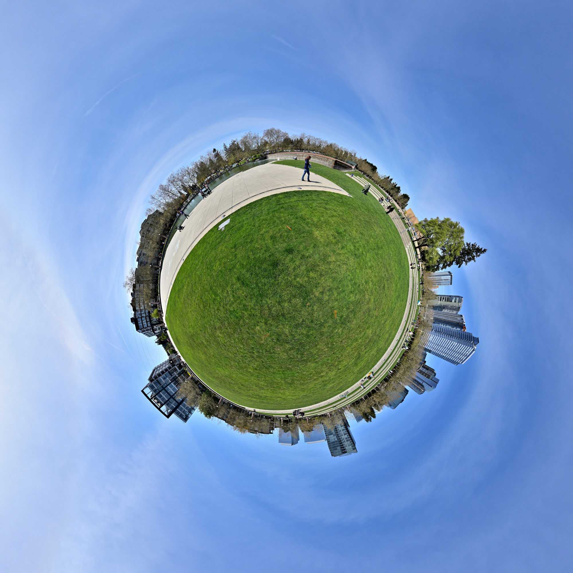
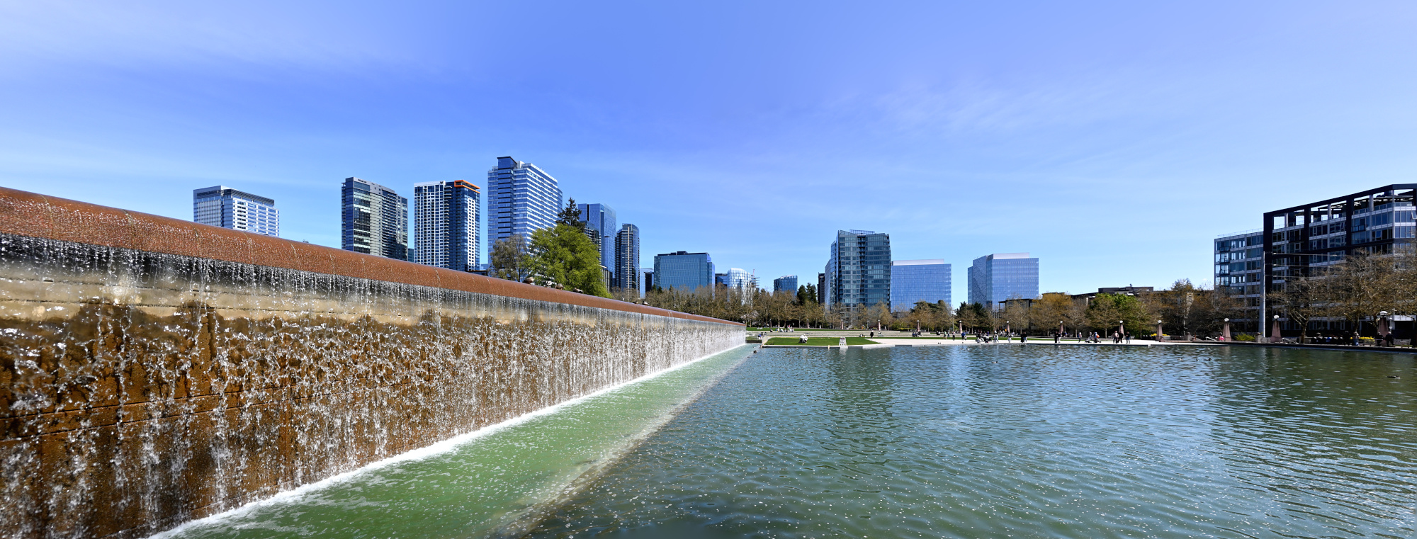
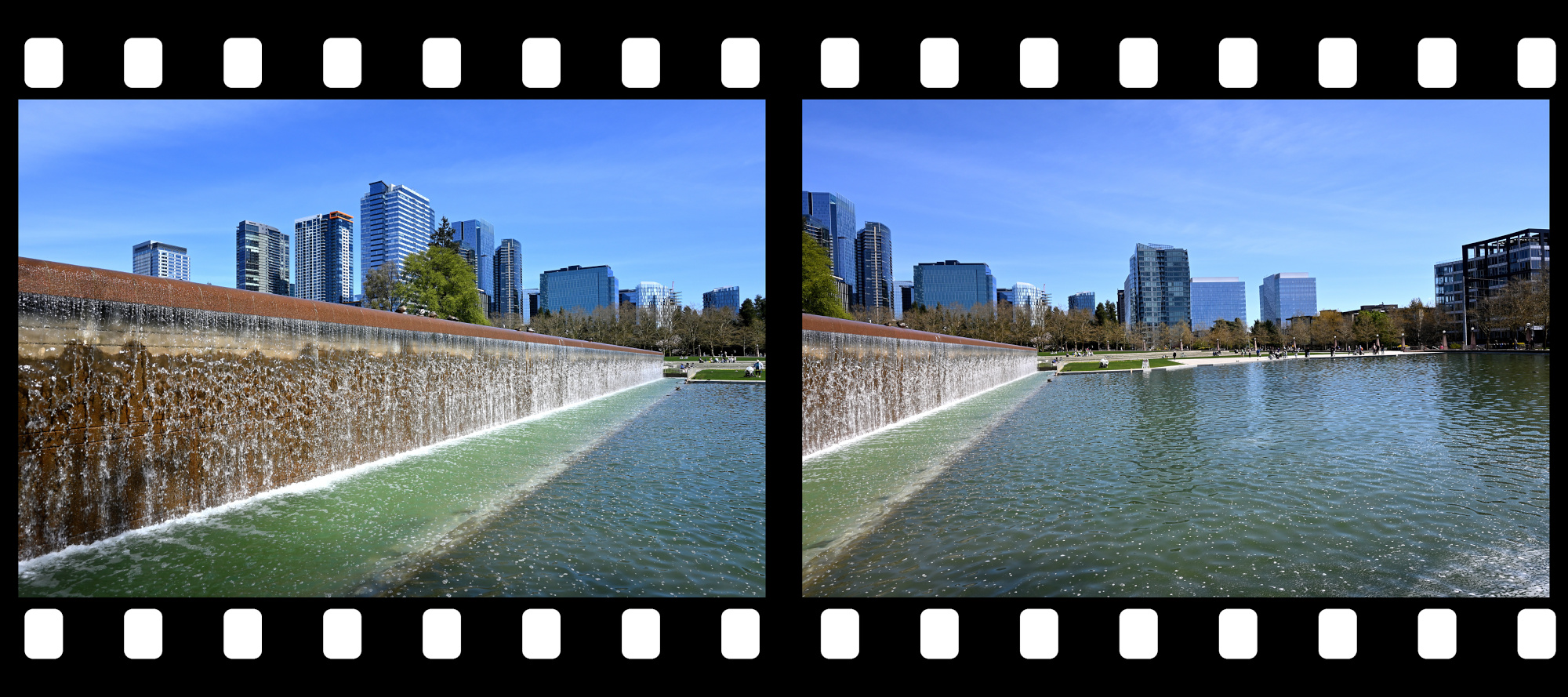
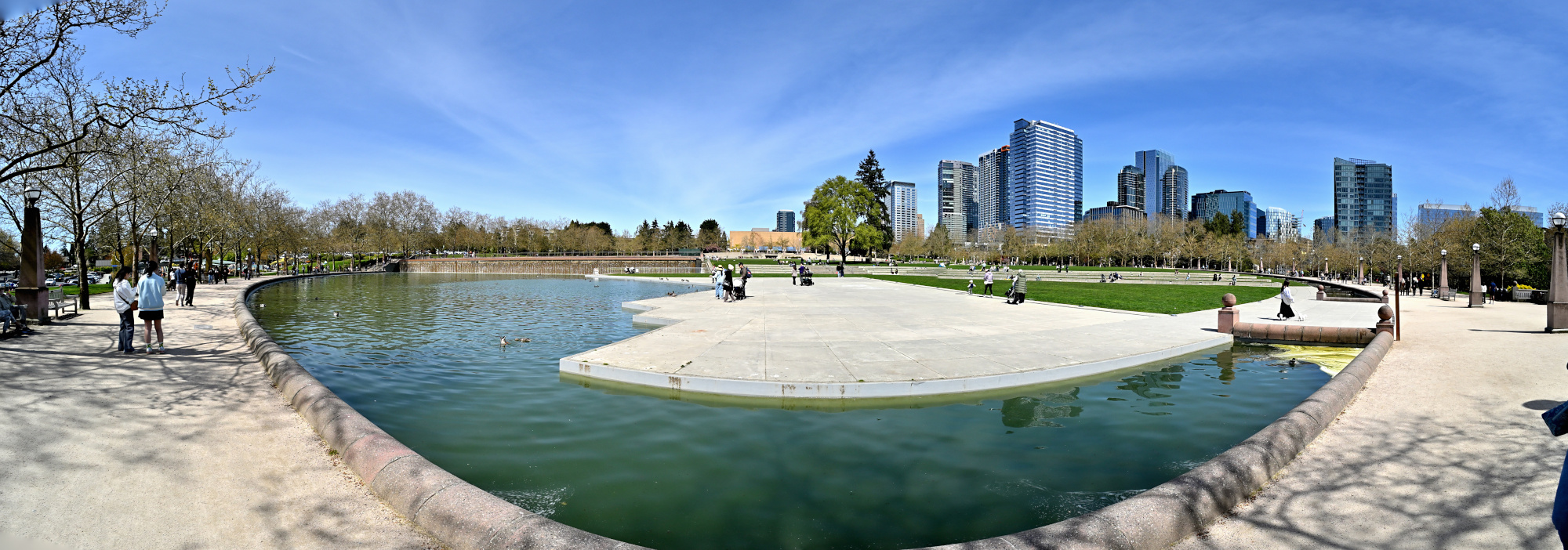
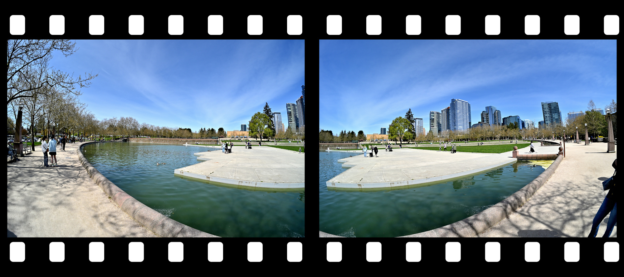
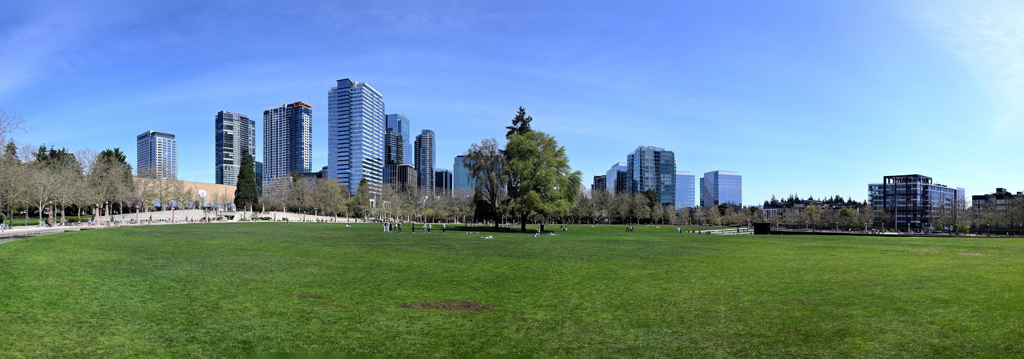
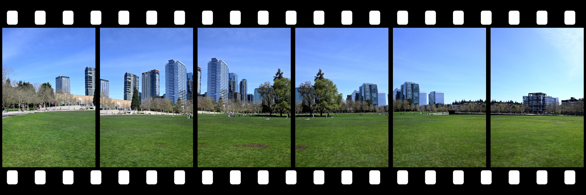
Bellevue Downtown Park
Sunny Sunday afternoon at the Bellevue Downtown Park.
Interactive Panorama Bellevue Downtown Park 1
1/800s f/5,6 ISO 100/21° f=7,5mm
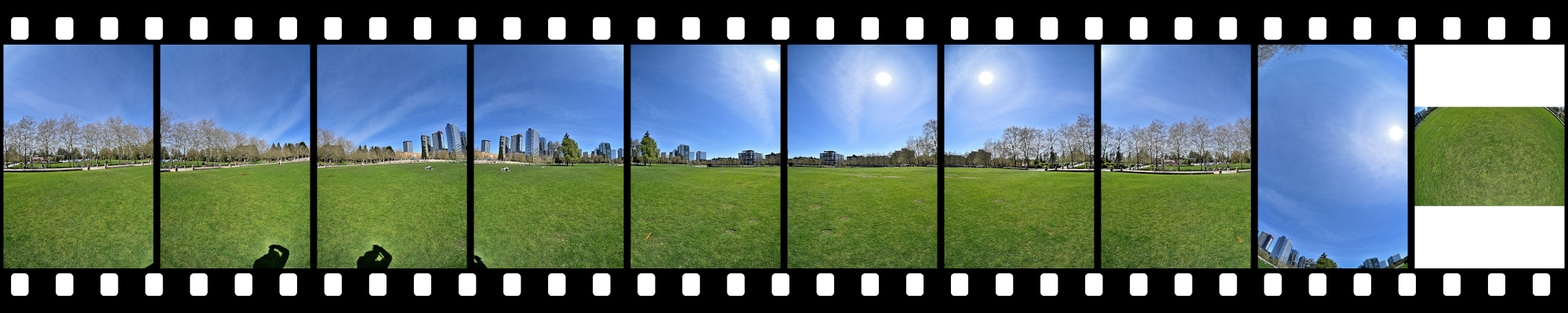
Interactive Panorama Bellevue Downtown Park 2
1/800s f/5,6 ISO 100/21° f=7,5mm
Lake 1
1/400s f/7,1 ISO 100/21° 16-50mm f/3,5-6,3 VR f=16mm/24mm
Lake 2
1/1000s f/5,6 ISO 100/21° f=7,5mm
Lake 3
1/400s f/7,1 ISO 100/21° 16-50mm f/3,5-6,3 VR f=16mm/24mm
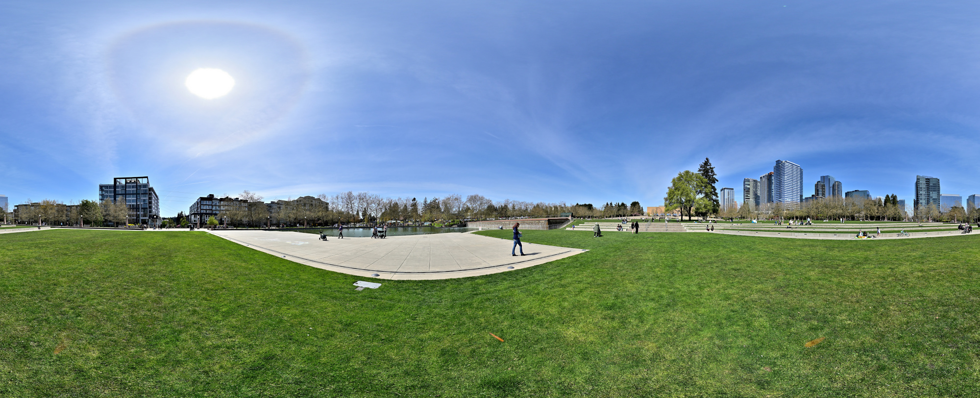
Downtown View
1/400s f/7,1 ISO 100/21° 16-50mm f/3,5-6,3 VR f=24mm/36mm
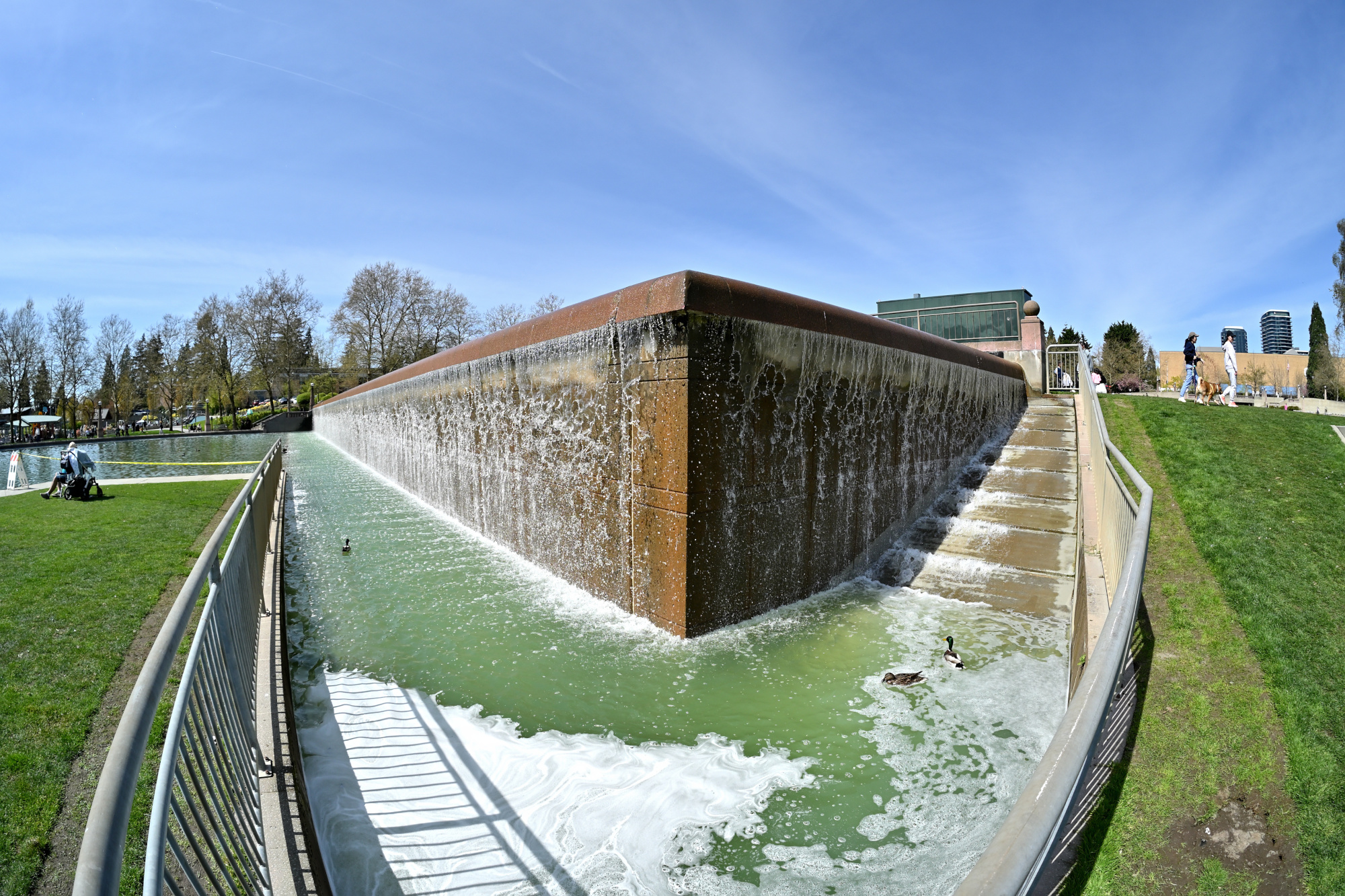
Duck's corner
Fisheye lens captures the corner of the waterfall, a favorite haunt for 🦆
1/800s f/5,6 ISO 100/21° f=7,5mm
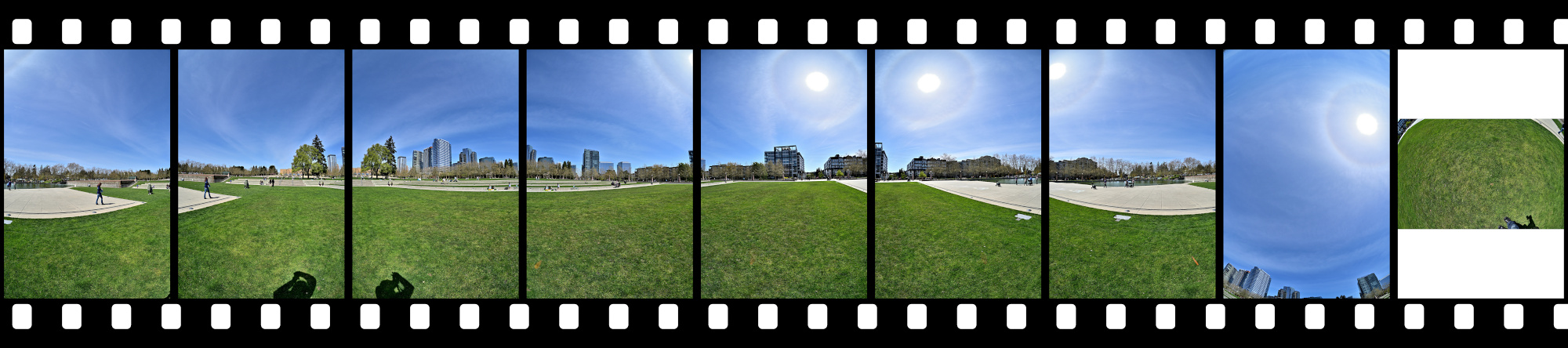
Different projections:
[Cylindric] [Equirectangular] [Mercator] [Rectangular] [Vedutsimo]